


2.3
SETTING UP WITH A DMX512
CONTROLLER
2.3-1 DMX512 ADDRESSING WITHOUT ID ADDRESSING
(
STAGE 1 MODE)
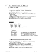
Connect the DMX512 controller to the units in series.
Each unit has 9 DMX channels so the DMX Addresses should increase by
increments of
9 (e.g. 1,10,19,28...)
The ID address has not been set so therefore when using the controller Ch9
must be inactive ( CH9=0 ).
Each DMX Address may be used as many times as required.
Any DMX address in the range from 001 to 512 may be used.
Example:
2 INSTALLATION
2009.12.9
6
The figure above shows a simple DMX512
layout with the starting address of the first
unit set at 1, with the second set at 10 and
so on... (Note that when used in this way,
the CH9 ID function must be inactive (CH9=0))
2.3-2 DMX512 ADDRESSING WITH ID ADDRESS
(
STAGE 1 MODE)
Connect the DMX512 controller to the units in series
Each unit has 9DMX channels so the DMX Addresses should increase by
increments of 9 (e.g. 1,10,19,28...)
Each DMX Address may be used as many times as required.
Any DMX address in the range from 001 to 512 may be used.
Each DMX address may carry up to 66 separate ID addresses.
ID
should be set in the menu on each unit in ascending values
(i.e. 1,2,3...)
ID addresses are accessible from Ch9 on the DMX512 controller.
Summary of Contents for MIINI COLOR 7 TC
Page 1: ...11 ...
Page 4: ...1 3 TECHNICAL SPECIFICATIONS LED MODULE 1 PRODUCT GENERAL 2 2009 12 9 ...
Page 5: ...1 4 PHOTOMETRIC DATA PHOTOMETRIC DATA 1 PRODUCT GENERAL 3 2009 12 9 ...
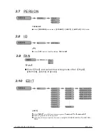
Page 11: ...3 DISPLAY PANEL OPERATION 2009 12 9 9 3 2 MENU ...
Page 16: ...14 4 USING A DMX512 CONTROLLER 2009 12 9 ...
Page 17: ...15 4 USING A DMX512 CONTROLLER 2009 12 9 ...
Page 19: ...17 4 USING A DMX512 CONTROLLER 2009 12 9 5 1 TROUBLE SHOOTING LED MODULE 5 APPENDIX ...


