1
6
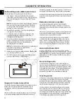
“dc-0” means that no DTCs were found, while “dc-4”
means that four DTCs are recorded.
5. Press the select button to cycle through the list of
DTCs.
6. Once the last DTC is displayed, “CLr?” appears.
Press and hold the select button until “Hold” changes
to “Done,” which indicates that all DTCs have been
“cleared” from ECM memory.
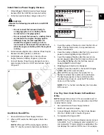
7. Disconnect service power supply connector for a
minimum of 20 seconds. See A of Figure 1-2.
8. Connect service power supply connector.
9. The tool displays the number of DTCs read.
10. Press the select button to cycle through the list of
DTCs. Write down each DTC as it is displayed.
Use Diagnostic Tool to Read/Clear DTCs
1. Obtain Briggs & Stratton Diagnostic Tool (Part No.
19636) with USB and Interface cables.
2. Connect one end of the USB cable to the Diagnostic
Tool and the other end to the USB port on the laptop.
3. Connect one end of the Interface cable to the
Diagnostic Tool and the other end to the DLC on the
EFI harness.
4. Turn Ignition ON, Engine OFF. The Diagnostic Tool
can take up to 30 seconds to connect to the engine.
Dashboard
icon (
A
) in the
left sidebar to view the
Dealer
tab.
6. Observe the Current codes display (
B
).
NOTE:
The
CHECK ENGINE
light (
C
) is green if a
current fault code is present. To display a description
of the fault code, hover the cursor over the code.
4
NOTE:
A Current codes display can also be viewed
under the
Troubleshooting
tab.
7. Click
Clear
(
D
) to erase both current and historic
DTCs.
NOTE:
See the Briggs & Stratton EFI Diagnostic Tool
Software User Manual for more information.
8. Turn Ignition OFF.
Back Probe Connector Terminals
NOTE:
Do not insert probes into terminals on the mating
side of any connector. The diameter of the test probes
can damage terminals.
1. Obtain Briggs & Stratton Back Probe Wire Set (Part
No. 19625).
2. Carefully slide metal pin on probe between the rubber
seal and wire insulation on the back side (wire end) of
the connector.
3. Gently push the pin in until it stops. Stop pushing
when the pin “bottoms out,” or when the plastic
sheath is very close to the connector housing.
DO NOT
force the pin into the connector as terminal
and/or probe pin damage can occur. Probe travel
may be stopped by contact with insulation or core
crimps. Try again after removing and re-positioning
probe pin.
IMPORTANT:
• Use care to avoid deforming connector terminals,
either by forcing the probe too far into the cavity
or by using a probe that is too large. If terminal
damage is suspected, test for proper terminal
contact.
• A deformed terminal can cause a poor
connection resulting in intermittent problems or
even complete component failure. Do not use
paper clips or other substitute devices as they
also can damage terminals.
• Do not probe through connector seals, wire
insulation, secondary ignition wires, boots, etc.
Damage can occur that is not readily apparent
and tiny holes can result in water intrusion, which
leads to corrosion and eventual component
failure.
Avoid ECM Damage
CAUTION
A surge in voltage, current or both, is called a
voltage spike. Voltage spikes can cause major
damage to the ECM.
Not for
Reproduction
Summary of Contents for Vanguard EFI 380000
Page 2: ...N o t f o r R e p r o d u c t i o n ...
Page 6: ...N o t f o r R e p r o d u c t i o n ...
Page 12: ...1 8 N o t f o r R e p r o d u c t i o n ...
Page 64: ...2 60 N o t f o r R e p r o d u c t i o n ...
Page 68: ...3 64 MODEL 380000 EFI ELECTRICAL SCHEMATIC N o t f o r R e p r o d u c t i o n ...
Page 82: ...4 78 N o t f o r R e p r o d u c t i o n ...
Page 85: ...5 81 This page is intentionally left blank N o t f o r R e p r o d u c t i o n ...
Page 95: ...5 91 This page is intentionally left blank N o t f o r R e p r o d u c t i o n ...
Page 96: ...5 92 17 N o t f o r R e p r o d u c t i o n ...
Page 98: ...5 94 This page is intentionally left blank N o t f o r R e p r o d u c t i o n ...


