background image

2

45

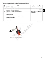
DTC P0520/P0524 ENGINE OIL PRESSURE SWITCH FAULT

Circuit Description

The normally closed contacts of the oil pressure switch

are held open by engine oil pressure when the engine is

running. If oil pressure drops below 7-10 psi, the contacts

close to complete a circuit to ground, and DTC P0524 is

set.

The ECM will also check to verify a closed circuit (switch

contacts closed) when the engine is not running. The

Service Power Supply Harness (Part No. 847252) must

be used to do this check. If an open circuit is detected,

then DTC P0520 is displayed after a delay of 30 seconds

(but the code is not stored).

Diagnostic Aids

Check for the following conditions:
1. Poor ECM connection or oil pressure switch terminal

connection.

2. Inspect wire harness connectors for backed out

terminals, improper mating, broken locks, improperly

formed or damaged terminals, and poor terminal to

wire connection.

3. Damaged wire harness and/or connectors. If harness

appears to be OK, shake or wiggle wire harness

and/or connector with DVOM attached. Radical

voltage changes can indicate the location of the fault

condition.

 Always clear DTCs after performing repairs.

Not for 

Reproduction

Summary of Contents for Vanguard EFI 380000

Page 1: ...21829EN Revision A BRIGGS STRATTON LLC CUSTOMER EDUCATION Milwaukee WI 53201 USA Copyright 2020 All rights reserved VANGUARDPOWER COM Vanguard EFI Diagnostic and Repair 380000 REPAIR MANUAL N o t f o r R e p r o d u c t i o n ...

Page 2: ...N o t f o r R e p r o d u c t i o n ...

Page 3: ...cedures described in this manual are appropriate for the Briggs Stratton engines described herein Alternative methods or procedures may pose risks to both personal safety and engine reliability and are not endorsed or recommended by Briggs Stratton All information illustrations and specifications contained in this manual were based on the data available at the time of publication Briggs Stratton L...

Page 4: ...engine models MODEL 380000 NOTE Some models have limited service parts Review the Illustrated Parts List for part availability before conducting any service work NOTE The images in this document are representative and may differ according to model N o t f o r R e p r o d u c t i o n ...

Page 5: ...SECTION 1 DIAGNOSTIC INTRODUCTION 1 SECTION 2 TROUBLESHOOTING DTCs 2 SECTION 3 WIRE SCHEMATICS AND PIN OUTS 3 SECTION 4 SYMPTOMS 4 SECTION 5 REMOVAL INSTALLATION 5 N o t f o r R e p r o d u c t i o n ...

Page 6: ...N o t f o r R e p r o d u c t i o n ...

Page 7: ...on Indicator Lamp MIL 4 Data Link Connector DLC 4 Non Scan Diagnostics 4 Scan Diagnostics 4 Install Service Power Supply Harness 5 Use MIL to Read DTCs 5 Use Tiny Scan Code Reader to Read Clear DTCs 5 Use Diagnostic Tool to Read Clear DTCs 6 Back Probe Connector Terminals 6 Avoid ECM Damage 6 Special Tools 7 N o t f o r R e p r o d u c t i o n ...

Page 8: ...tor Lamp MIL As a bulb and diagnostic system check the MIL illuminates when the engine is cranked If it does not illuminate during cranking then a problem exists in the MIL circuit When the engine is started the MIL is extinguished if no current fault condition exists If the MIL flashes it is an indication that a current DTC is stored If the fault should correct itself as in an intermittent condit...

Page 9: ... four digits If the first digit is zero it is represented as a series of ten flashes 4 Count the number of flashes after the first one second pause to obtain the second digit of the DTC 5 Count the number of flashes after the second one second pause to obtain the third digit and then count the number of flashes after the third one second pause to obtain the fourth digit 6 Write down each digit as ...

Page 10: ... DTCs NOTE See the Briggs Stratton EFI Diagnostic Tool Software User Manual for more information 8 Turn Ignition OFF Back Probe Connector Terminals NOTE Do not insert probes into terminals on the mating side of any connector The diameter of the test probes can damage terminals 1 Obtain Briggs Stratton Back Probe Wire Set Part No 19625 2 Carefully slide metal pin on probe between the rubber seal an...

Page 11: ... terminal If electric welding on vehicle remove battery negative cable black from battery negative terminal and disconnect the ECM electrical connector s Special Tools The following special tools are required 1 Briggs Stratton Spark Tester Part No 19368 2 Briggs Stratton Digital Volt Ohmmeter Extech Ma220 Part No 19602 3 Briggs Stratton Noid Light Part No 19623 4 Briggs Stratton BIG BLOCK Fuel Pre...

Page 12: ...1 8 N o t f o r R e p r o d u c t i o n ...

Page 13: ...ignal Voltage Low Non Scan Diagnostics 22 DTC P0113 Signal Voltage High Scan Diagnostics 24 DTC P0113 Signal Voltage High Non Scan Diagnostics 25 DTC P0117 P0118 ENGINE HEAD TEMPERATURE EHT SENSOR 26 Circuit Description 26 Diagnostic Aids 26 DTC P0117 Signal Voltage Low Scan Diagnostics 27 DTC P0117 Signal Voltage Low Non Scan Diagnostics 28 DTC P0118 Signal Voltage High Scan Diagnostics 29 DTC P0...

Page 14: ...Switch Circuit Open or Grounded Non Scan Diagnostics 46 DTC P0524 Engine Low Oil Pressure Non Scan Diagnostics 47 DTC P0562 P0563 ECM OUTPUT SUPPLY VOLTAGE 48 Circuit Description 48 Diagnostic Aids 48 DTC P0562 System Voltage Low Scan Diagnostics 49 DTC P0562 ECM Output Supply Voltage Low Non Scan Diagnostics 50 DTC P0563 System Voltage High Scan Diagnostics 52 DTC P0563 ECM Output Supply Voltage ...

Page 15: ...o B Fuel Pump Module P0230 Signal Voltage Low Open or High Cylinder 1 Ignition Coil P0351 Circuit Open or Grounded Cylinder 2 Ignition Coil P0352 Circuit Open or Grounded P0506 RPM Low P0507 RPM High Throttle Actuator Motor P2102 Driver Circuit Open or Grounded P0520 Switch Circuit Open or Grounded Engine Oil Pressure Switch P0524 Low Oil Pressure P0562 Supply Voltage Low ECM Output Supply Voltage...

Page 16: ...Probing Connector x or Replacing Component o To Access Air Cleaner Assembly Fuel Pump Module Cover Blower Housing ECM xo Throttle Actuator Motor xo MAP MAT Sensor xo xo xo Ignition Coil xo xo o Mechanical Diaphragm Fuel Pump o Fuel Pump Module xo Fuel Injector xo xo NOTE See SECTION 5 REMOVAL INSTALLATION for instructions N o t f o r R e p r o d u c t i o n ...

Page 17: ...ting proper voltage Check ECM Power and Grounds Non Scan Diagnostics Step Action Yes No 1 1 Back probe terminal J11 Red wire of ECM connector 2 Connect terminal J11 back probe to red meter test lead on DVOM 3 Back probe terminal J9 Black wire of ECM connector 4 Connect terminal J9 back probe to black meter test lead on DVOM 5 Set DVOM to read volts DC 6 Observe voltage on DVOM while cranking engin...

Page 18: ...l back to the ECM on terminal J22 according to the manifold pressure value on the terminal Diagnostic Aids Check for the following conditions 1 Poor ECM connection Inspect wire harness connectors for backed out terminals improper mating broken locks improperly formed or damaged terminals and poor terminal to wire connection 2 Damaged wire harness and or connectors If harness appears to be OK shake...

Page 19: ...icon in the left sidebar and then the Troubleshooting tab 2 Observe the MAP Voltage display with or without the engine running 3 Is reading 0 5 4 5 volts DC MAP sensor circuit OK Go to step 2 2 Is reading below 0 5 volts DC Go to DTC P0107 Non Scan Diagnostics N o t f o r R e p r o d u c t i o n ...

Page 20: ...k probe to red meter test lead on DVOM 4 Back probe terminal 4 Brown wire of MAP sensor connector 5 Connect terminal 4 back probe to black meter test lead on DVOM 6 Set DVOM to read volts DC 7 Connect service power supply connector 8 Observe voltage 9 Is reading 4 6 5 0 volts DC Go to step 3 Go to step 3 3 1 Disconnect service power supply connector 2 Remove probe from terminal 2 and back probe EC...

Page 21: ...connect service power supply connector 2 Remove probe from terminal 1 and back probe ECM connector terminal J22 White Red wire 3 Connect service power supply connector 4 Observe voltage on DVOM 5 Is reading 3 7 4 2 volts DC EFI wire harness OK Replace MAP sensor Go to step 6 6 1 Not getting ground thru 5 volt return circuit 2 Are both MAP sensor and ECM connectors fully mated Repair or replace EFI...

Page 22: ... icon in the left sidebar and then the Troubleshooting tab 2 Observe the MAP Voltage display with or without the engine running 3 Is reading 0 5 4 5 volts DC MAP sensor circuit OK Go to step 2 2 Is reading above 4 5 volts DC Go to DTC P0108 Non Scan Diagnostics N o t f o r R e p r o d u c t i o n ...

Page 23: ...red meter test lead on DVOM 4 Back probe terminal 4 Brown wire of MAP sensor connector 5 Connect terminal 4 back probe to black meter test lead on DVOM 6 Set DVOM to read volts DC 7 Connect service power supply connector 8 Observe voltage on DVOM 9 Is reading 4 7 5 0 volts DC Go to step 3 3 1 Disconnect service power supply connector 2 Remove probe from terminal 2 and back probe terminal 1 White R...

Page 24: ...g conditions 1 Poor ECM connection 2 Inspect wire harness connectors for backed out terminals improper mating broken locks improperly formed or damaged terminals and poor terminal to wire connection 3 Damaged wire harness and or connectors If harness appears to be OK shake or wiggle wire harness and or connector with DVOM or Diagnostic Tool connected Radical voltage changes or a change in the MAT ...

Page 25: ...icon in the left sidebar and then the Troubleshooting tab 2 Observe the IAT Voltage display with or without the engine running 3 Is reading 0 5 4 5 volts DC MAT sensor circuit OK Go to step 2 2 Is reading below 0 5 volts DC Go to DTC P0112 Non Scan Diagnostics N o t f o r R e p r o d u c t i o n ...

Page 26: ...ead on DVOM 4 Back probe terminal 4 Brown wire of MAT sensor connector 5 Connect terminal 4 back probe to black meter test lead on DVOM 6 Set DVOM to read volts DC 7 Connect service power supply connector 8 Observe voltage on DVOM 9 Is reading 4 7 5 0 volts DC MAT sensor OK Go to step 3 3 1 Disconnect service power supply connector 2 Remove probe from terminal 2 and back probe terminal 3 Tan Black...

Page 27: ...erminal J25 Tan Black wire 3 Connect service power supply connector 4 Observe voltage on DVOM 5 Is reading 0 5 4 5 volts DC MAT sensor circuit OK Go to step 5 5 Are both MAT sensor and ECM connectors fully mated Repair or replace EFI wire harness Connect connectors Service Power Supply Connector N o t f o r R e p r o d u c t i o n ...

Page 28: ... icon in the left sidebar and then the Troubleshooting tab 2 Observe the IAT Voltage display with or without the engine running 3 Is reading 0 5 4 5 volts DC MAT sensor circuit OK Go to step 2 2 Is reading above 4 5 volts DC Go to DTC P0113 Non Scan Diagnostics N o t f o r R e p r o d u c t i o n ...

Page 29: ...meter test lead on DVOM 4 Back probe terminal 4 Brown wire of MAT sensor connector 5 Connect terminal 4 back probe to black meter test lead on DVOM 6 Set DVOM to read volts DC 7 Connect service power supply connector 8 Observe voltage on DVOM 9 Is reading 4 7 5 0 volts DC MAT sensor OK Go to step 3 3 1 Disconnect service power supply connector 2 Remove probe from terminal 2 and back probe terminal...

Page 30: ... conditions 1 Poor ECM connection 2 Inspect wire harness connectors for backed out terminals improper mating broken locks improperly formed or damaged terminals and poor terminal to wire connection 3 Damaged wire harness and or connectors If harness appears to be OK shake or wiggle wire harness and or connector with DVOM or Diagnostic Tool connected Radical voltage changes or a change in the EHT s...

Page 31: ...icon in the left sidebar and then the Troubleshooting tab 2 Observe the EHT Voltage display with or without the engine running 3 Is reading 0 5 4 5 volts DC EHT sensor circuit OK Go to step 2 2 Is reading below 0 5 volts DC Go to DTC P0117 Non Scan Diagnostics N o t f o r R e p r o d u c t i o n ...

Page 32: ...24 back probe to red meter test lead on DVOM 4 Back probe terminal J26 Brown wire of ECM connector 5 Connect terminal J26 back probe to black meter test lead on DVOM 6 Set DVOM to read volts DC 7 Connect service power supply connector 8 Observe voltage on DVOM 9 Is reading 0 5 4 5 volts DC EHT sensor OK Go to step 3 3 1 Reading is below 0 5 volts DC 2 Is ECM connector fully mated EHT sensor is bad...

Page 33: ... icon in the left sidebar and then the Troubleshooting tab 2 Observe the EHT Voltage display with or without the engine running 3 Is reading 0 5 4 5 volts DC EHT sensor circuit OK Go to step 2 2 Is reading above 4 5 volts DC Go to DTC P0118 Non Scan Diagnostics N o t f o r R e p r o d u c t i o n ...

Page 34: ...24 Tan wire of ECM connector 3 Connect terminal J24 back probe to red meter test lead on DVOM 4 Back probe terminal J26 Brown wire of ECM connector 5 Connect terminal J26 back probe to black meter test lead on DVOM 6 Set DVOM to read volts DC 7 Connect service power supply connector 8 Observe voltage on DVOM 9 Is reading 0 5 4 5 volts DC EHT sensor OK Reading is above 4 5 volts DC EHT sensor is ba...

Page 35: ...TE If an ignition coil fault code is active the fuel injector will not inject fuel to the cylinder with the faulty ignition coil Diagnostic Aids Check for the following conditions 1 Poor ECM connection 2 Inspect wire harness connectors for backed out terminals improper mating broken locks improperly formed or damaged terminals and poor terminal to wire connection 3 Damaged wire harness and or conn...

Page 36: ...e fuel injector Go to step 3 3 1 Connect service power supply connector 2 Does Noid Light flash Check charging circuit between stator and ECM Refer to DTC P0562 P0563 Go to step 4 4 1 Disconnect service power supply connector 2 Remove Noid Light and connect fuel injector connector 3 Back probe using fused patch cord terminal A Red wire of fuel injector connector 4 Connect terminal A back probe to ...

Page 37: ...VOM 9 Is reading less than 0 1 ohms Go to step 6 Reading is above 0 1 ohms Check terminals for corrosion or replace EFI wire harness NOTE If DTC still present after replacement of EFI wire harness then replace ECM 6 1 Remove probe from terminal B and back probe terminal A Red wire of fuel injector connector 2 Observe resistance on DVOM 3 Is reading less than 0 1 ohms Replace ECM Reading is above 0...

Page 38: ...the ECM activates the fuel pump module The fuel pump module delivers fuel to the fuel rail and fuel injector Diagnostic Aids The following conditions may have caused the fuel pump to malfunction 1 Intermittent short in the fuel pump power feed circuit 2 Fuel pump has an intermittent internal problem 3 Poor ECM connection 4 Inspect wire harness connectors for backed out terminals improper mating br...

Page 39: ...t lead on DVOM 4 Connect black meter test lead on DVOM to a known good ground 5 Set DVOM to read volts DC 6 Connect service power supply connector 7 Does DVOM read 12 2 13 5 volts DC Go to step 4 Go to DTC P0562 4 1 Disconnect service power supply connector 2 Disconnect fuel pump module connector 3 Remove probe from terminal 2 and back probe terminal 1 Blue Yellow wire of fuel pump module connecto...

Page 40: ... fault is set the ECM shuts down the fuel injection to the same cylinder The engine continues to run on one cylinder if no fault code is set for the opposite cylinder Diagnostic Aids Check for the following conditions 1 Poor ECM connection 2 Inspect wire harness connectors for backed out terminals improper mating broken locks improperly formed or damaged terminals and poor terminal to wire connect...

Page 41: ...for spark in tester windows 4 Is spark observed Go to step 3 See Vanguard OHV V Twin Repair Manual 3 1 Check ignition coil harness for damaged wires and faulty connections 2 Is a problem found Repair Go to step 4 4 1 Back probe terminal J1 White wire of ECM connector 2 Connect terminal J1 back probe to red meter test lead on DVOM 3 Connect probe of black meter test lead on DVOM to cylinder 1 ignit...

Page 42: ...minal C White wire of ignition coil connector ignition harness side 2 Observe resistance on DVOM 3 Is reading 0 1 ohms or less Go to step 7 Inspect pin and socket halves of ignition coil harness connector for loose or backed out terminals Repair as necessary 7 1 Remove probe from terminal C of ignition coil connector EFI wire harness side and probe cylinder 1 ignition coil spade terminal 2 Observe...

Page 43: ...or spark in tester windows 4 Is spark observed Go to step 3 See Vanguard OHV V Twin Repair Manual 3 1 Check ignition coil harness for damaged wires and faulty connections 2 Is a problem found Repair Go to step 4 4 1 Back probe terminal J18 White wire of ECM connector 2 Connect terminal J18 back probe to red meter test lead on DVOM 3 Connect probe of black meter test lead on DVOM to cylinder 2 igni...

Page 44: ...minal A White wire of ignition coil connector ignition harness side 2 Observe resistance on DVOM 3 Is reading 0 1 ohms or less Go to step 7 Inspect pin and socket halves of ignition coil harness connector for loose or backed out terminals Repair as necessary 7 1 Remove probe from terminal A of ignition coil connector EFI wire harness side and probe cylinder 2 ignition coil spade terminal 2 Observe...

Page 45: ...ions connector is connected for 50 Hz and disconnected for 60 Hz Verify correct connect disconnect based on application For non generator applications without a variable speed control verify correct speed No speed change could indicate faulty speed circuit wires or connector If equipped with variable speed control look for the appropriate speed change when the control is actuated No speed change o...

Page 46: ...t throttle actuator motor connector 3 Back probe terminal 1 Brown wire of throttle actuator motor connector 4 Connect terminal 1 back probe to red meter test lead on DVOM 5 Disconnect ECM connector 6 Back probe terminal J32 Brown wire of ECM connector 7 Connect terminal J32 back probe to black meter test lead on DVOM 8 Set DVOM to read resistance 9 Does DVOM read 0 5 ohm or less Go to step 3 Resis...

Page 47: ...l J15 and back probe terminal J14 White Red wire of ECM connector 3 Does DVOM read 0 5 ohm or less Go to step 5 Resistance reading is above 0 5 ohm Check terminals for corrosion or replace EFI wire harness 5 1 Remove probe from terminal 4 and back probe terminal 6 Tan Black wire of throttle actuator motor connector 2 Remove probe from terminal J14 and back probe terminal J31 Tan Black wire of ECM ...

Page 48: ...e terminal J9 Black wire of ECM connector 5 Connect terminal J9 back probe to black meter test lead on DVOM 6 Set DVOM to read volts DC 7 Does DVOM read 12 2 13 5 volts DC while cranking engine Go to step 3 No power going to throttle actuator motor Go to DTC P0562 P0563 3 1 Remove probe from terminal 2 and back probe terminal 5 Red wire of throttle actuator motor connector 2 Does DVOM read 12 2 13...

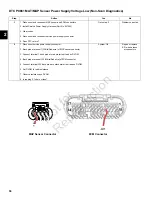
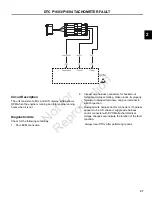
Page 49: ...eck If an open circuit is detected then DTC P0520 is displayed after a delay of 30 seconds but the code is not stored Diagnostic Aids Check for the following conditions 1 Poor ECM connection or oil pressure switch terminal connection 2 Inspect wire harness connectors for backed out terminals improper mating broken locks improperly formed or damaged terminals and poor terminal to wire connection 3 ...

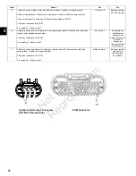
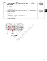
Page 50: ...en wire of ECM connector 3 Connect terminal J30 back probe to red meter test lead on DVOM 4 Disconnect oil pressure switch connector 5 Connect black meter test lead on DVOM to spade socket terminal 6 Set DVOM to read resistance 7 Observe resistance on DVOM 8 Is reading 0 1 ohms or less Green wire is OK Go to step 3 Repair or replace EFI wire harness or connectors 3 1 Connect red meter test lead on...

Page 51: ...ch wire shorting to ground Repair Go to step 3 Replace oil pressure switch 3 1 Install Service Power Supply Harness Part No 847252 2 Clear codes 3 Disconnect code reader 4 Disconnect and reconnect service power supply connector 5 Wait for 30 seconds to elapse 6 Connect code reader 7 Does DTC return Check oil pump See Vanguard OHV V Twin Repair Manual Problem corrected Service Power Supply Connecto...

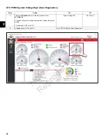
Page 52: ...ly used for powering the EFI system Any battery charge system that may be supplied does not provide power to the EFI system Diagnostic Aids Check for the following conditions 1 Poor ECM connection 2 Inspect wire harness connectors for backed out terminals improper mating broken locks improperly formed or damaged terminals and poor terminal to wire connection 3 Damaged wire harness and or connector...

Page 53: ...ard icon in the left sidebar to view the Dealer tab 2 Observe the Ignition Voltage display with or without the engine running 3 Is reading 9 0 15 0 volts DC System voltage OK Go to step 2 2 Is reading below 9 0 volts DC Go to DTC P0562 Non Scan Diagnostics N o t f o r R e p r o d u c t i o n ...

Page 54: ... probe terminal J9 Black wire of ECM connector 5 Connect terminal J9 back probe to black meter test lead on DVOM 6 Set DVOM to read volts DC 7 Observe voltage on DVOM while cranking engine 8 Is reading 12 16 volts DC System OK Go to step 3 3 1 Disconnect fuel pump module fuel injector and throttle actuator motor connectors 2 Observe voltage on DVOM while cranking engine 3 Is reading 12 16 volts DC...

Page 55: ... terminal 2 back probe to black meter test lead on DVOM 6 Set DVOM to read volts AC 7 Observe voltage on DVOM while cranking engine 8 Is reading 44 52 volts AC Go to step 8 Replace stator 8 1 Remove probe from terminal 2 and back probe terminal J3 Yellow wire of ECM connector 2 Set DVOM to read resistance 3 Observe resistance on DVOM 4 Is reading 0 1 ohms or less Go to step 9 Repair or replace EFI...

Page 56: ...ard icon in the left sidebar to view the Dealer tab 2 Observe the Ignition Voltage display with or without the engine running 3 Is reading 9 0 15 0 volts DC System voltage OK Go to step 2 2 Is reading above 15 0 volts DC Go to DTC P0563 Non Scan Diagnostics N o t f o r R e p r o d u c t i o n ...

Page 57: ... 2 1 Disconnect service power supply connector 2 Back probe terminal J11 Red wire of ECM connector 3 Connect terminal J11 back probe to red meter test lead on DVOM 4 Back probe terminal J9 Black wire of ECM connector 5 Connect terminal J9 back probe to black meter test lead on DVOM 6 Set DVOM to read volts DC 7 Observe voltage on DVOM while cranking engine 8 Is reading 12 16 volts DC System OK Go ...

Page 58: ... to step 4 Replace stator 4 1 Remove probe from terminal 2 and back probe terminal J3 Yellow wire of ECM connector 2 Set DVOM to read resistance 3 Observe resistance on DVOM 4 Is reading 0 1 ohms or less Go to step 5 Repair or replace EFI wire harness stator connector 5 1 Remove probe from terminal J3 and back probe terminal J5 Yellow wire of ECM connector 2 Remove probe from terminal 1 and back p...

Page 59: ...ic Aids Check for the following conditions 1 Poor ECM connection 2 Inspect wire harness connectors for backed out terminals improper mating broken locks improperly formed or damaged terminals and poor terminal to wire connection 3 Damaged wire harness and or connectors If harness appears to be OK shake or wiggle wire harness and or connector with DVOM attached Radical voltage changes can indicate ...

Page 60: ...rrected 2 1 Disconnect service power supply connector 2 Back probe terminal 1 White Red wire of MAP sensor connector 3 Connect terminal 1 back probe to red meter test lead on DVOM 4 Back probe terminal J22 White Red wire of ECM connector 5 Connect terminal J22 back probe to black meter test lead on DVOM 6 Set DVOM to read resistance 7 Observe resistance on DVOM 8 Is reading 0 1 ohms or less System...

Page 61: ...nection 2 Inspect wire harness connectors for backed out terminals improper mating broken locks improperly formed or damaged terminals and poor terminal to wire connection 3 Damaged wire harness and or connectors If harness appears to be OK shake or wiggle wire harness and or connector with DVOM attached Radical voltage changes can indicate the location of the fault condition Always clear DTCs aft...

Page 62: ...ed meter test lead on DVOM 3 Back probe terminal J9 Black wire of ECM connector 4 Connect terminal J9 back probe to black meter test lead on DVOM 5 Set DVOM to read volts DC 6 Observe voltage on DVOM while cranking engine 7 Is reading greater than 9 volts DC Replace tachometer Go to step 3 3 1 Disconnect service power supply connector 2 Remove probe from terminal J9 and back probe terminal A Red w...

Page 63: ...epair or replace EFI wire harness or connectors 5 1 Remove probe from terminal B and back probe terminal C Black Red wire of tachometer connector 2 Remove probe from terminal J9 and back probe terminal J16 Black Red wire of ECM connector 3 Connect terminal J16 back probe to black meter test lead on DVOM 4 Observe resistance on DVOM 5 Is reading 0 1 ohms or less Replace tachometer Repair or replace...

Page 64: ...2 60 N o t f o r R e p r o d u c t i o n ...

Page 65: ...3 61 SECTION 3 WIRE SCHEMATICS AND PIN OUTS ECM CONNECTOR PIN OUT 62 MODEL 380000 EFI ELECTRICAL SCHEMATIC 64 N o t f o r R e p r o d u c t i o n ...

Page 66: ...tput MPR Throttle Actuator Motor If Equipped J12 NOT USED J13 NOT USED J14 White Red Throttle Actuator Motor Control A J15 Red White Throttle Actuator Motor Control B J16 Black Red Tachometer J17 Blue Yellow Fuel Pump J18 White Cylinder 2 Ignition Coil Signal Input J19 NOT USED J20 NOT USED J21 NOT USED J22 White Red Manifold Absolute Pressure MAP Sensor J23 Black Engine Speed Select Connector Dis...

Page 67: ...D J30 Green Oil Pressure Switch J31 Tan Black Throttle Actuator Motor Control C J32 Brown Throttle Actuator Motor Control D J33 Yellow CAN Lo Used only for ECM to ECM communication J34 Green CAN Hi Used only for ECM to ECM communication N o t f o r R e p r o d u c t i o n ...

Page 68: ...3 64 MODEL 380000 EFI ELECTRICAL SCHEMATIC N o t f o r R e p r o d u c t i o n ...

Page 69: ...RODUCTION 66 ENGINE DOES NOT CRANK 67 ENGINE CRANKS BUT DOES NOT START 68 ENGINE EXHIBITS HARD START SYMPTOMS 70 ENGINE POWER OUTPUT LOW 71 ENGINE HUNTS AND SURGES 73 ECM CONNECTOR SYMPTOMS 76 N o t f o r R e p r o d u c t i o n ...

Page 70: ... both core and insulation crimps Intermittents IMPORTANT Intermittents may not cause the MIL to illuminate or set a DTC DO NOT use the DTC Tables to diagnose intermittent problems The fault condition must be present to locate the problem Many intermittent problems are caused by faulty electrical connections or wiring The engine may be operated with a DVOM connected to the suspect circuit If an abn...

Page 71: ...anguard OHV V Twin Repair Manual Is a problem found Repair Go to step 6 6 Verify starter is operating properly See Vanguard OHV V Twin Repair Manual Is a problem found Repair Go to step 7 7 Review diagnostic procedures in this table If all steps have been completed and no problems have been found proceed as follows Repeat visual check Review Diagnostic Tool Code reader data Check all electrical co...

Page 72: ... Repair Go to step 6 6 Verify that fuel pressure is 38 43 psi 262 296 kPa See CHECK RELIEVE FUEL SYSTEM PRESSURE in SECTION 5 REMOVAL INSTALLATION Is a problem found Repair Go to step 7 7 Verify safety interrupt is NOT active or faulty if equipped Is a problem found Repair Go to step 8 8 Verify that each cylinder is getting spark See Vanguard OHV V Twin Repair Manual Is a problem found Repair Go t...

Page 73: ...as follows Repeat visual check Review Diagnostic Tool Code reader data Check all electrical connections within the suspect circuit and or system Is a problem found Repair Go to step 12 12 Carefully review data under ECM CONNECTOR SYMPTOMS in this section Is a problem found Repair Contact engine manufacturer N o t f o r R e p r o d u c t i o n ...

Page 74: ...LLATION Is a problem found Repair Go to step 5 5 Check for intermittent opens or shorts to ground in MAP sensor circuit Is a problem found Repair Go to step 6 6 Check engine for the following mechanical problems Low compression Leaking cylinder head gaskets Proper valve set up See Vanguard OHV V Twin Repair Manual Is a problem found Repair Go to step 7 7 Review diagnostic procedures in this table ...

Page 75: ...em found Repair Go to step 5 5 Verify crankcase oil is at the correct level Is a problem found Add crankcase oil Go to step 6 6 Verify air filter element is clean and dry Is a problem found Replace air filter element Go to step 7 7 Verify engine is not supporting a greater load than intended for its application Check for the following Damaged drive belt For mowers verify blades are not restricted ...

Page 76: ... procedures in this table If all steps have been completed and no problems have been found proceed as follows Repeat visual check Review Diagnostic Tool Code reader data Check all electrical connections within the suspect circuit and or system Is a problem found Repair Go to step 12 12 Carefully review data under ECM CONNECTOR SYMPTOMS in this section Is a problem found Repair Contact engine manuf...

Page 77: ... oil is at the correct level Is a problem found Add crankcase oil Go to step 6 6 Verify air filter element is clean and dry Is a problem found Replace air filter element Go to step 7 7 Verify governor is set up properly See Vanguard OHV V Twin Repair Manual for mechanical governor information Is a problem found Repair Go to step 8 8 Inspect governor link spring for damage or improper installation ...

Page 78: ...le actuator motor as far from throttle body as possible alternately tighten screws to 9 13 in lbs 1 2 Nm d If throttle lever rotation is still not stopped by the dead idle screw loosen two throttle body to intake manifold screws Moving throttle actuator motor bracket away from throttle body tighten two throttle body to intake manifold screws to 70 in lbs 8 Nm Adjust dead idle screw to 1200 RPM typ...

Page 79: ...4 75 Step Action Yes No 13 Carefully review data under ECM CONNECTOR SYMPTOMS in this section Is a problem found Repair Contact engine manufacturer N o t f o r R e p r o d u c t i o n ...

Page 80: ...mp Injector Power Output MPR Red Will not run J12 NOT USED J13 NOT USED J14 Throttle Actuator A White Red Governed speed unstable or incorrect J15 Throttle Actuator B Red White Governed speed unstable or incorrect J16 Tachometer Black Red Tachometer inoperative J17 Fuel Pump Blue Yellow Will not run J18 Cylinder 2 Ignition Coil Signal Input White Misfire backfire afterfire will not run rough idle ...

Page 81: ...ressure Switch Green Incorrect oil pressure signal J31 Throttle Actuator C Tan Black Governed speed unstable or incorrect J32 Throttle Actuator D Brown Governed speed unstable or incorrect J33 CAN Lo for ECM to ECM Communication Only Yellow For service diagnostics or communication with other ECM J34 CAN Hi for ECM to ECM Communication Only Green For service diagnostics or communication with other ...

Page 82: ...4 78 N o t f o r R e p r o d u c t i o n ...

Page 83: ... Air Cleaner Assembly 83 Fuel Pump Module Cover 83 Blower Housing 83 ECM 85 MAP MAT Sensor 85 Ignition Coil 85 Fuel Filter 85 Mechanical Diaphragm Fuel Pump 85 Fuel Pump Module 86 Fuel Rail Fuel Injector 87 Throttle Actuator Motor 87 EHT Sensor 88 EFI Wire Harness 89 MECHANICAL DIAPHRAGM FUEL PUMP FOR MODEL 380000 93 Volumetric Test 93 N o t f o r R e p r o d u c t i o n ...

Page 84: ...uel pressure test adapter between fuel rail and fuel pump module 7 Remove protective cap from Schrader valve on fuel pressure test adapter and install fuel pressure gauge 8 Connect fuel pump module connector Push in grey secondary lock to secure 9 Install new cable strap to secure fuel pump module connector conduit to socket pin housing 10 Cut cable strap to release fuel injector connector conduit...

Page 85: ...5 81 This page is intentionally left blank N o t f o r R e p r o d u c t i o n ...

Page 86: ...5 82 6 NOTE Air cleaner assembly and fuel pump module cover removed for illustration purposes N o t f o r R e p r o d u c t i o n ...

Page 87: ...nugly into air filter element 7 Install thumb nut B onto threaded rod and tighten until snug 8 Install air filter cover A 9 Engage two retaining clips to secure air filter cover Fuel Pump Module Cover Removal 1 Loosen or remove six Phillips screws to release front and top of cover from fuel pump module bracket 2 Loosen two Phillips screws to release side of cover from cover bracket 3 Access inboar...

Page 88: ...ackplate flanges 2 On cylinder 1 side proceed as follows A Start two lower hex flange screws to fasten blower housing to heat shield and flywheel backplate flanges B Start upper inside hex flange screw to fasten lifting eye mechanical diaphragm fuel pump bracket blower housing and heat shield flange to intake manifold C Start upper outside hex flange screw to fasten lifting eye mechanical diaphrag...

Page 89: ...emove ignition coil See Vanguard OHV V Twin Repair Manual Installation 1 Install ignition coil See Vanguard OHV VTwin Repair Manual 2 Connect ignition coil connector 3 See Blower Housing Installation 4 See Air Cleaner Assembly Installation Fuel Filter Removal 1 Relieve fuel system pressure See CHECK RELIEVE FUEL SYSTEM PRESSURE in this section 2 Squeeze hose clip and remove fuel inlet hose from fu...

Page 90: ...cket pin housing Pull out grey secondary lock and press to disconnect fuel pump module connector B 5 Squeeze two tabs on quick disconnect fitting to release fuel rail from fuel outlet port C NOTE Wrap shop towel around fitting to catch any fuel leakage 6 Squeeze hose clip at fuel inlet port D and remove hose from mechanical diaphragm fuel pump 7 Remove three hex screws to release fuel pump module ...

Page 91: ...h clean engine oil 2 Install fuel injector into throttle body 3 Install retaining clip to secure fuel injector cap to fuel injector Orient retaining clip as noted during removal Be sure retaining clip is fully engaged 4 Install hex flange screw to fasten fuel injector cap flange to throttle body Tighten screw to 104 122 lb in 12 14 Nm 5 Connect fuel injector connector 6 Install new cable strap to ...

Page 92: ...otor lever in the stopped position verify that throttle lever makes contact with the dead idle screw 7 If throttle lever rotation is not stopped by the dead idle screw but by contact with the throttle link loosen two throttle body to intake manifold screws 8 See D of Figure 13 Moving throttle actuator motor bracket away from throttle body tighten two throttle body to intake manifold screws to 70 l...

Page 93: ...ensor bracket from ECM bracket Installation 1 Position EFI wire harness at top of intake manifold separating conduit and connectors into three groups as shown in Figure 15 2 See C of Figure 15 Proceed as follows Install hex screw to fasten EHT sensor bracket to ECM bracket Tighten screw to 15 25 lb in 2 3 Nm Install hex flange screw to fasten ECM ground wire ring terminal to ECM bracket Tighten sc...

Page 94: ...r 1 high tension lead Install cable strap if missing See E of Figure 16 F Install new cable strap to secure fuel injector connector conduit to fuel injector socket pin housing See F of Figure 16 5 See Blower Housing Installation NOTE Fuel pump module connector is connected during blower housing installation Be sure to install new cable strap to secure fuel pump module connector conduit to socket p...

Page 95: ...5 91 This page is intentionally left blank N o t f o r R e p r o d u c t i o n ...

Page 96: ...5 92 17 N o t f o r R e p r o d u c t i o n ...

Page 97: ...uated cylinder See the table below for the approximate amount of fuel that should be discharged Pump Fuel for 30 Seconds 237 m 0 5 pint 0 25 quart Approximate Fuel Amount 1 0 cup NOTES Position the fuel tank so that it is near level with the fuel pump Do not place the graduated cylinder BELOW the fuel pump or gravity feed will produce false results The engine will run longer than the 30 second tes...

Page 98: ...5 94 This page is intentionally left blank N o t f o r R e p r o d u c t i o n ...

Page 99: ...N o t f o r R e p r o d u c t i o n ...

Page 100: ...21829EN Revision A BRIGGS STRATTON LLC CUSTOMER EDUCATION Milwaukee WI 53201 USA Copyright 2020 All rights reserved VANGUARDPOWER COM Vanguard EFI Diagnostic and Repair 380000 REPAIR MANUAL N o t f o r R e p r o d u c t i o n ...

Reviews: