Not for
Reproduction
Page | i
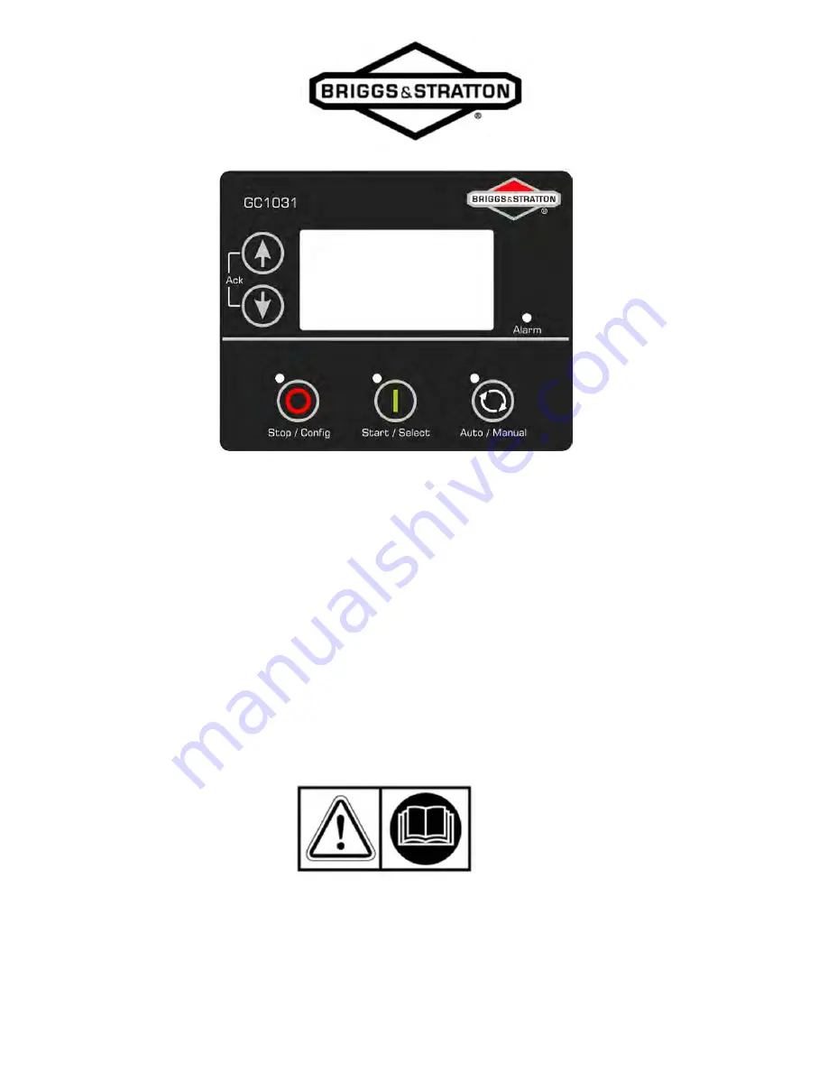
Operation Instructions
GC1031
GENSET Controller
Copyright © Briggs &
Stratton Corporation 80086364
Milwaukee, WI USA. All Rights Reserved. Revision A
Page 1: ...N o t f o r R e p r o d u c t i o n Page i Operation Instructions GC1031 GENSET Controller Copyright Briggs Stratton Corporation 80086364 Milwaukee WI USA All Rights Reserved Revision A ...
Page 2: ...erious injury WARNING indicates a hazardous situation which if not avoided could result in death or serious injury CAUTION indicates a hazardous situation which if not avoided could result in minor or moderate injury NOTICE indicates a situation which can cause damage to the equipment personal property and or the environment or cause the equipment to operate incorrectly WARNING Failure to read und...
Page 3: ...U Genset Control Unit Genset Generator Set GND Ground GST Gain Schedule Trigger HMI Human Machine Interface HSD High Side Driver HWT High Water Temperature ID Identifier LCD Liquid Crystal Display LED Light Emitting Diode LIM Low Idle Mode LLOP Low Lube Oil Pressure LOP Lube Oil Pressure LVL Level MCP Manual Control Panel MPU Magnetic Pickup Unit OV Over Voltage PF Power Factor PID Proportional In...
Page 4: ... 1 Description of Control Keys 4 2 Functions of Control Keys 4 2 1 Configuration of GCU 5 3 List of Parameters 5 3 1 Operating Modes 14 4 Auto Mode 14 4 1 Auto Mains Failure AMF 14 4 1 1 Remote Start Stop 2 Wire 16 4 1 2 Auto Exercise Mode 16 4 1 3 Manual Mode 17 4 2 Low Idle Mode LIM 18 4 2 1 Alarms 19 5 Troubleshooting 21 6 Notes 24 ...
Page 5: ...troller from the backside 1 Figure 2 Control key function 4 Figure 3 Configuration mode screen 5 Figure 4 Configuration mode authentication page screen 5 Figure 5 Saving settings screen 5 Figure 6 SMD for AMF mode 15 Figure 7 SMD for auto exercise mode 17 Figure 8 SMD for manual mode 18 ...
Page 6: ...les Table 1 Voltage input terminology 2 Table 2 Details of the GC1031 terminals 2 Table 3 Control keys in different modes 4 Table 4 Parameters 5 Table 5 Alarm actions 19 Table 6 Alarms and their causes 19 Table 7 Common faults and their remedial actions 21 ...
Page 7: ...tegration RPM sensing using frequency and MPU Supports Auto Exercise Modes Real time clock based event logs PC connectivity via USB port RS485 CAN J1939 protocol Backlit and full graphics display with power saving feature Installation 1 Terminal Description 1 1 The figure that follows shows the rear view of the controller Figure 1 GC1031 Genset controller from the backside ...
Page 8: ...5 RS485_B RS485 B 16 RS485_A RS485 A 17 GOV_ACT OUT1 Output for the Actuator 1 18 GOV_ACT OUT4 Output for the Actuator 4 19 GOV_ACT OUT2 Output for the Actuator 2 20 GOV_ACT OUT3 Output for the Actuator 3 21 DIG_IN D Input from switch D 22 DIG_IN E Input from switch E 23 ANLG_V IN Analog input 4 20mA for LOP or 2 5 2V 24 ANLG_IN ENG_TEMP Analog input from Engine Temperature Sensor 25 ANLG_IN Fuel ...
Page 9: ... B L3 36 CT IN B2 CT input 2 from Phase B L3 37 CT IN Y1 CT input 1 from Phase Y L2 38 CT IN Y2 CT input 2 from Phase Y L2 39 CT IN R1 CT input 1 from Phase R L1 40 CT IN R2 CT input 2 from Phase R L1 41 SENSOR COMM Sensor common point 42 MPU I P Speed Sensor Input from engine speed sensor Inductive ...
Page 10: ...t Start Exits LIM and operates at normal speed 2 Manual Auto Enters Auto Mode Stop Stops the engine when engine is running Stop long pressed Enters Configuration Mode Stop Down long pressed Enters Programming Mode 3 Auto Stop Stops the engine and enters Manual Mode 4 Manual Auto Configuration Up Down Scrolls the screens parameter 5 Manual Auto Up Down Acknowledges and clears the alarm 6 Configurat...
Page 11: ... the digit The 4 digits will start blinking individually as each one is selected Press the START button as mentioned earlier to enter the correct digit After completion of the parameter configuration push and hold the STOP key to exit from configuration mode Before exiting from the configuration mode the controller will show the following screen Figure 5 Saving settings screen List of Parameters 3...
Page 12: ...kdays 1 28 days Start Time EXER START TIME 00 00 23 59 hour Exercise Skip Enable EXER SKIP ENABLE Yes No 45 min Burn Off 45 MIN BURN OFF 45 min Burn Off 45 MIN BURN OFF Disable Enable Event Month EVENT MONTH 1 March April May None Event Day EVENT DAY 1 1 28 Start Time EVENT START TIME 1 00 00 23 59 hour Event Month EVENT MONTH 2 August September October None Event Day EVENT DAY 2 1 28 Start Time E...
Page 13: ... Enable Low Fuel Level Shutdown Threshold SHUTDOWN THRESHOLD 0 78 Low Fuel Level Notification NOTIFICATION Disable Enable Low Fuel Level Notification Threshold NOTIFICATION THRESH 2 80 Fuel Tank Capacity FUEL TANK CAPACITY 2 1000 litre Fuel Theft Warning FUEL THEFT ALARM Disable Enable Fuel Theft Alarm Threshold FUEL THEFT THRESHOLD 1 100 per hour Circuit Fault Action CKT FAULT ACTION None Notific...
Page 14: ... ACTION None Notification Warning Electrical Trip Shutdown Digital Activation DIG ACTIVATION Never From Engine Start From Monitoring On Always Digital Activation Delay DIG ACTIVATION DELAY 1 60 sec Shutdown SHUTDOWN Disable Enable Shutdown Threshold SHUTDOWN THRESHOLD 0 0 9 8 0 0 9 8 Bar Warning WARNING Disable Enable Warning Threshold WARNING THRESHOLD 0 2 10 0 0 2 10 0 Bar Circuit Fault Action C...
Page 15: ... CNFG TMR 10 1800 sec Generator GENERATOR Alternator Configuration ALT CONFIG Alternator Present ALT PRESENT No Yes Number Of Poles NUMBER OF POLES 2 4 6 8 AC system ALT AC SYSTEM Single Phase 2 Wire Single Phase 3 Wire Three Phase 4 Wire 1Ph 2 wire 1Ph 3 wire 3Ph 4 wire Min Healthy Voltage MIN HEALTHY VOLT 50 350 Volt Ph N Min Healthy Frequency MIN HEALTHY FREQ 10 75 Hz Phase Reversal Detection P...
Page 16: ... Warning UNDER FREQ WARNING Disable Enable Under frequency Warning Threshold UF WARNING THRESHOLD 11 0 60 0 Hz Over frequency Shutdown OVER FREQ SHUTDOWN Disable Enable Over frequency Shutdown Threshold OF SHUTDWN THRESHLD 26 0 75 0 Hz Over frequency Warning OVER FREQ WARNING Disable Enable Over frequency Warning Threshold OF WARNING THRESHOLD 25 0 74 0 Hz Current Monitoring CURRENT MONITOR CT Rat...
Page 17: ...e 4 Wire 1Ph 2 wire 1Ph 3 wire 3Ph 4 wire Phase Reversal Detection PHASE REVERSE DETECT Disable Enable Phase Reversal Action PHASE REVERSE ACTION None Notification Warning Electrical Trip Shutdown Under voltage Monitoring UNDER VOLT MON Under voltage ENABLE Disable Enable Trip TRIP 50 298 Volt Ph N Return RETURN 52 300 Volt Ph N Over voltage Monitoring OVER VOLT MON Over voltage ENABLE Disable Ena...
Page 18: ... Engine Speed Sense Source SPEED SENSE SOURCE Sensor input only Alternator output only Primary Sensor Secondary Alternator Primary Alternator Secondary Sensor Flywheel Teeth FLYWHEEL TEETH 1 300 Under speed Shutdown UNDER SPEED SHUTDOWN Disable Enable Under speed Threshold UNDER SPD THRESHOLD 0 3600 rpm Under speed Delay UNDER SPD DELAY 1 60 sec Over speed Threshold OVER SPD THRESHOLD 700 4500 rpm...
Page 19: ...tor Direction ACTUATOR DIRECTION Clockwise Anti Clockwise to Stop Engine Start Strategy ENG START STRGY Cranking Steps CRANKING STEPS 5 5000 Initial Low Speed Delay INIT LOW SPEED DELAY 0 180 sec Initial Low Speed INIT LOW SPEED 500 1800 RPM PID Trigger Speed PID TRIGGER SPEED 20 2800 RPM Ramp Up Time RAMP UP TIME 1 180 sec PID on Time PID ON TIME 1 180 sec LIM P Gain LIM P GAIN 0 1000 LIM I Gain ...
Page 20: ...s can only be changed by the dealer while others can only be changed by the manufacturer designated by an Some default parameters are subject to change during firmware updates per the manufacturer The dealer password is available on the Briggs and Stratton Power Portal Operating Modes 4 There are two modes of operation Auto Mode Manual Mode Auto Mode 4 1 To enter Auto Mode push the AUTO key While ...
Page 21: ...o the Mains further it will stop the genset after a cool down period Figure 6 SMD for AMF mode Engine Cooling Down in LIM Mains ON 1 or Electric trip Mains 0 and No Warning No Electric Trip No Shutdown Engine Off Engine On Engine Start Emergency shutdown input 1 Or Genset shutdown action 1 Time Time of warm up Time of load transfer and Mains ON 0 and Remote start 1 ...
Page 22: ...t will have 6 runtime options It will have a default 0 1min 6s cycle enabled with an option to choose from 5min 10min 15min 20min None runtimes The selected runtime can be scheduled to run once weekly monthly The run is dependent on the ambient temperature of the genset If the ambient temperature is below 40ºF then the exercise will be skipped The skipping of the exercise based on ambient temperat...
Page 23: ... at the normal set speed exercise Exercise The genset will be ON even if the Mains is healthy during Auto Exercise Mode The load will not be transferred to genset even if Load transfer is enabled in configuration GCU will enter in LIM after the first 6 seconds of Auto Exercise Exercise start time is reached and No Warning Electrical Trip Shutdown Present Engine OFF Engine Start Engine ON LIM Engin...
Page 24: ...and will ignore non critical faults Engine Starts in LIM Genset healthy condition is as follows Voltage and frequency of genset above minimum threshold GCU will enter in LIM at first start command Second start command will exit LIM and will run in Normal Mode Engine cooling down in LIM Engine enters in Normal Mode Stop input from key 1 or Electric trip Engine Off Engine On Genset healthy condition...
Page 25: ...wn In this alarm the genset is immediately stopped Table 6 Alarms and their causes Sr No Alarms Causes 1 Low Oil Pressure Sensor Indicates that the oil pressure measured is below the pre set threshold 2 Low Oil Pressure Switch Indicates that the oil pressure measured is below the pre set threshold 3 High Oil Pressure Sensor Indicates that the oil pressure measured is above the pre set threshold 4 ...
Page 26: ...ceeded the pre set gross over speed threshold 26 Under Speed The engine speed has fallen below the pre set RPM 27 Extended Over Load Trip Indicates that there was 100 load on the genset for one hour in the time interval of last 12 hours 28 Battery Under Voltage The battery voltage has fallen below the pre set threshold 29 Battery Over Voltage The battery voltage has exceeded the pre set threshold ...
Page 27: ...g resulting in death or serious injury Before servicing stop the generator and disconnect the negative cable at the battery WARNING Electric shock hazard Electric shock could result in death or serious injury Do not install or remove current transformer when generator is operating Place generator in off position and remove controller fuse before servicing Disconnect all sources of electricity befo...
Page 28: ...essary Shutdown Alarms or Warning Alarms Check the respective switch sensor and wiring Enter Configuration Mode in the controller and verify the respective threshold configuration 5 The engine runs but the controller shows genset to be OFF Check if the MPU signal if used and main alternator voltage signal R L1 phase are received by the controller terminals Check if the LOP and LLOP are working OK ...
Page 29: ...ter Configuration Mode in the controller and verify the configuration for the Remote Stop digital input terminal Check that the controller is in Auto Mode 12 While in Auto Mode controller issues Start command even if the Mains present Check the wiring of the Mains R Y and B phase to the controller s respective input terminal Enter Configuration Mode in the controller and verify the configuration f...
Page 30: ...N o t f o r R e p r o d u c t i o n Page 24 Notes ...
Page 31: ...N o t f o r R e p r o d u c t i o n Page 25 Disclaimer Due to continuous development the details provided in this document are subject to change without any prior notice ...
Page 32: ...N o t f o r R e p r o d u c t i o n ...