


2
Safety
• Know the unit’s controls and how to stop quickly.
READ THE OPERATOR’S MANUALS.
• Read and obey all safety decals.
• Only allow responsible adults, who are familiar with
the instructions, to operate the unit.
• Disengage the PTO. Shut off the engine and wait
for all moving parts to stop before attaching,
adjusting, or disconnecting any part of the
collection system.
• Check the collection system to make sure it is
bolted tightly to the unit.
• DO NOT operate the unit without either the entire
grass catcher or the deflector in place.
• Turn off the PTO to disengage the blades when not
mowing.
• DO NOT mow in reverse unless absolutely
necessary. Always look down and behind before
and while travelling in reverse.
• DO NOT turn sharply when travelling alongside a
building or any object. Slow down before turning.
• DO NOT carry passengers.
• When collection system is removed from the
mower deck, the deflector must be properly
installed.
• Collector bags are subject to deterioration and
wear during normal use. Inspect the bag
periodically for tears, holes, or weak spots and
replace with a new bag that meets manufacturer’s
durability standards.
• If the mower stalls or the collector chute plugs:
1. Disengage the PTO;
2. Stop the engine and remove the key;
3. Set the parking brake, and wait for all moving
parts to stop.
4. Remove the foreign object or clear the chute
with a piece of wood before restarting the engine.
NEVER place hands into COLLECTOR OR
MOWER housing to clear jammed objects.
Blower OR MOWER may rotate when object is
removed.
• For added stability and to prevent tipping or loss of
control:
a. Use reduced speed on uneven ground and
when turning corners.
b. Reduce loads on hillsides. It is recommended
that the collection system be kept only half full
when negotiating any slopes. Start mowing on
slopes when the collection system is empty.
c. Mow up and down the face of slopes; never
across the face of any slope.
•
Never operate on slopes greater than 17.6%
(10°).
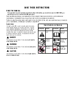
GENERAL WARNINGS
SAFETY DECALS
This unit has been designed and manufactured to
provide you with the safety and reliability you would
expect from an industry leader in outdoor power
equipment manufacturing.
Although reading this manual and the safety
instructions it contains will provide you with the
necessary basic knowledge to operate this equipment
safely and effectively, we have placed several safety
labels on the unit to remind you of this important
information while you are operating your unit.
All DANGER, WARNING, CAUTION and
instructional messages on your rider, attachments
and mower should be carefully read and obeyed.
Personal bodily injury can result when these
instructions are not followed. The information is for
your safety and it is important! The safety decals
below are on your product.
If any decals are lost or damaged, replace them at
once. See your local dealer for replacements.
TP 600-2562-01-AT-SMA
Attachment Decal
These labels are easily applied and will act as a
constant visual reminder to you, and others who may
use the equipment, to follow the safety instructions
necessary for safe, effective operation.
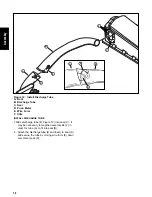
Thrown objects hazard
• Objects thrown by the mower can seriously
injure or kill you.
• Do not open the hopper while the mower blades
are turning.
• Do not operate the mower without the complete
catcher in place.
WARNING
1732819
Decal - WARNING Thrown
Objects Hazard
Part Number 1732819
Read and obey all operation and warning decals.
Summary of Contents for 1695353
Page 6: ...4 Notes ...


