Bridgeworks Appliance a202 Hardware Manual Download Page 8

The onboard Ethernet interfaces can be found at the back of the Appliance and are used for either

Management or WAN. See Section

2.1

:

Appliance Configuration

to see interface assignments.

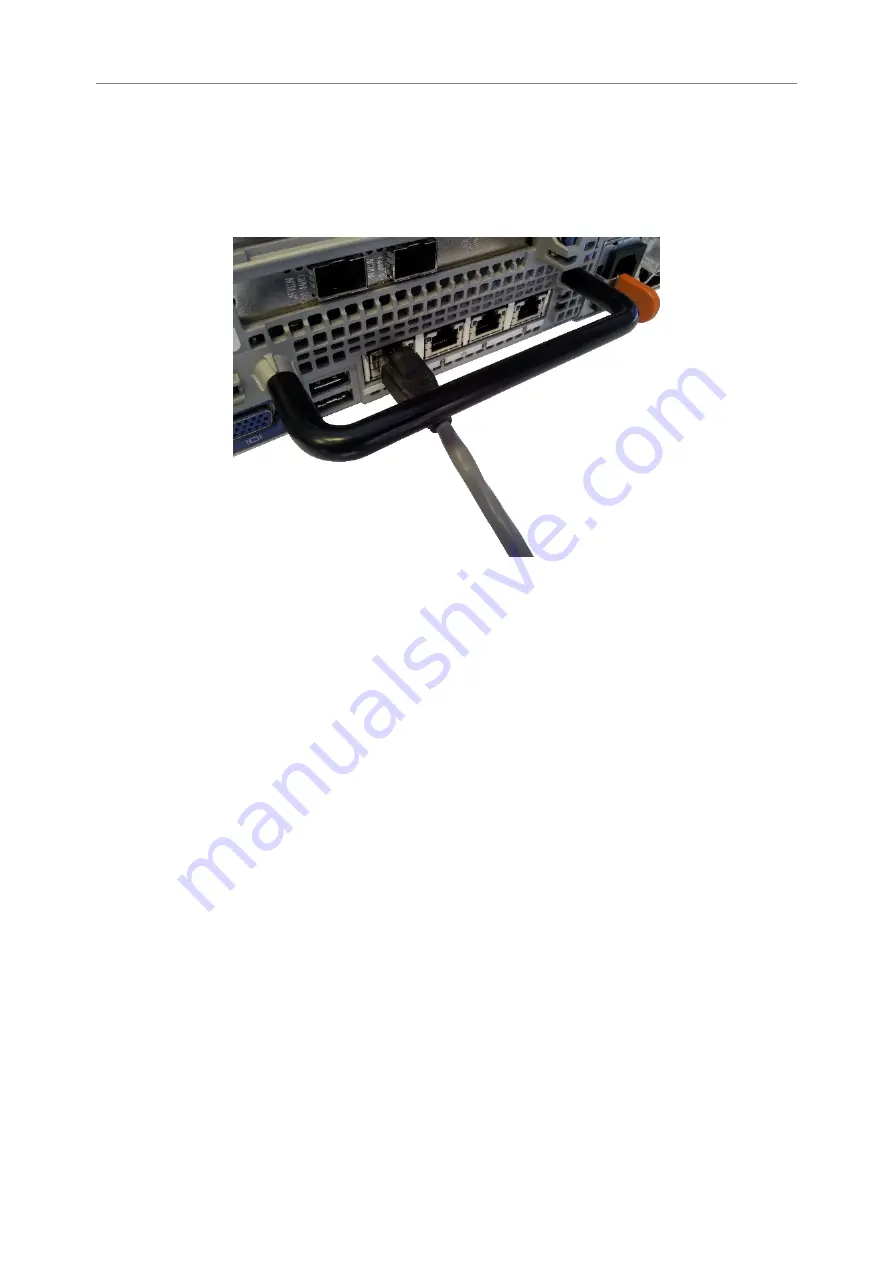
To connect an onboard interface, insert a Cat 5e cable (or better) into it as shown in the following

image. When the plug is in the correct position a “click” should be heard. The other end of the
cable should be connected to a network.

Rear Panel of the Appliance Showing Ethernet Cable Connections

2.3

Connecting the 10Gb Ethernet Cables

Depending on the configuration you have purchased, either one of the following cables will be
required for your product.

• LC Multi-mode Optical Fibre Cable (SFP+)

• Copper Interface Cable (SFP+)

• 10GBASE-T Category 6 or 6a Cable (RJ45)

2.3.1

Using a LC Multi-mode Optical Fibre Cable (SFP+)

If you have purchased a 10GBASE-SR feature card, connections up to 300 metres are supported
using OM3 or OM4 grade Multi-mode Optical Fibre 50/125 using LC connectors.

To connect the Appliance to an Ethernet network or directly to a device, insert one or two SFPs into

the unit.

8

Summary of Contents for Appliance a202

Page 1: ...Appliance a202 Hardware Manual Eli v5 02 153 Bridgeworks Unit 1 Aero Centre Ampress Lane Ampress Park Lymington Hampshire SO41 8QF Tel 44 0 1590 615 444 Email support 4bridgeworks com...

Page 2: ...de Optical Fibre Cable SFP Multi mode Optical Fibre 50 125 OM3 or OM4 Patch Cable LC up to 300 meters Or Copper Interface Cable SFP SFP Direct Attach Copper DAC Twin Ax interface cable passive up to 7...

Page 3: ...g the 10Gb Ethernet Cables 8 2 3 1 Using a LC Multi mode Optical Fibre Cable SFP 8 2 3 2 Using a Copper Interface Cable SFP 10 2 3 3 Using a 10GBASE T Category 6 or 6a Cable RJ45 10 2 4 Connecting the...

Page 4: ...quickly identify different pieces of information This icon represents a note of interest about a step or section of information This icon represents an important piece of information This icon repres...

Page 5: ...orised service center to perform any servicing inside the Appliance the user should not attempt to service any parts inside the unit themselves The power cord is used as a disconnection device be awar...

Page 6: ...t Certain models will use a Small Form factor Pluggable SFP Transceiver module for connection to an optical network These devices may use a Class 1 Laser device it is important that you do not stare i...

Page 7: ...nd can be used to identify the positions of the various feature cards available on your product Product Onboard Ports MA and MB Onboard Ports 8A and 8B WANrockIT 400 Management WAN WANrockIT 800 Manag...

Page 8: ...pliance Showing Ethernet Cable Connections 2 3 Connecting the 10Gb Ethernet Cables Depending on the configuration you have purchased either one of the following cables will be required for your produc...

Page 9: ...ome pre installed when a 10GBASE SR feature card has been purchased with your configuration Insert the multi mode cables in to the SFP as shown below When the plug is in the correct position a click s...

Page 10: ...6 and 100 meters for Category 6a To connect the Appliance to an Ethernet network or directly to a device connect one side of the Category 6 Ethernet cable into a RJ45 port located on a 10 Gigabit Eth...

Page 11: ...k speeds for each card are listed below Fibre Channel Card Speed Supported Link Speeds 8Gb 2Gb 4Gb 8Gb 16Gb 4Gb 8Gb 16Gb It is not necessary to specify which link speed you are using as the Appliance...

Page 12: ...r port Note By default WANrockIT units have the left hand port Port A as the target port and the right hand port Port B as the initiator port When the multi mode cables are inserted in to the SFP a cl...

Page 13: ...herals and interfaces are properly connected and are powered up To turn on the Appliance push the switch on the back as shown below Whenever the Appliance is powered on the switch will be illuminated...

Page 14: ...1 Ethernet 1 Link indicator 2 Activity indicator Link Activity Description Off Off Not connected Amber Connected at less than maximum speed Green Connected at maximum speed Flashing Green Data is bein...

Page 15: ...ental Operational temperature 10 C to 35 C Non operational temperature 40 C to 65 C Humidity 10 80 non condensing Onboard Management Interface No of interfaces 2 Physical RJ45 8P8C Speed Auto sensing...

Page 16: ...SE T RJ45 8P8C Speed Auto sensing 1000 10000Mb s Error Recovery ERL0 ERL1 ERL2 Standards IPv4 iSCSI iSNS CHAP DHCP Fibre Channel 8Gb Feature Card No of interfaces 2 Physical SFP mini GBIC Speed Auto s...

Reviews: