background image


Bridgeview Manufacturing Inc.


18 

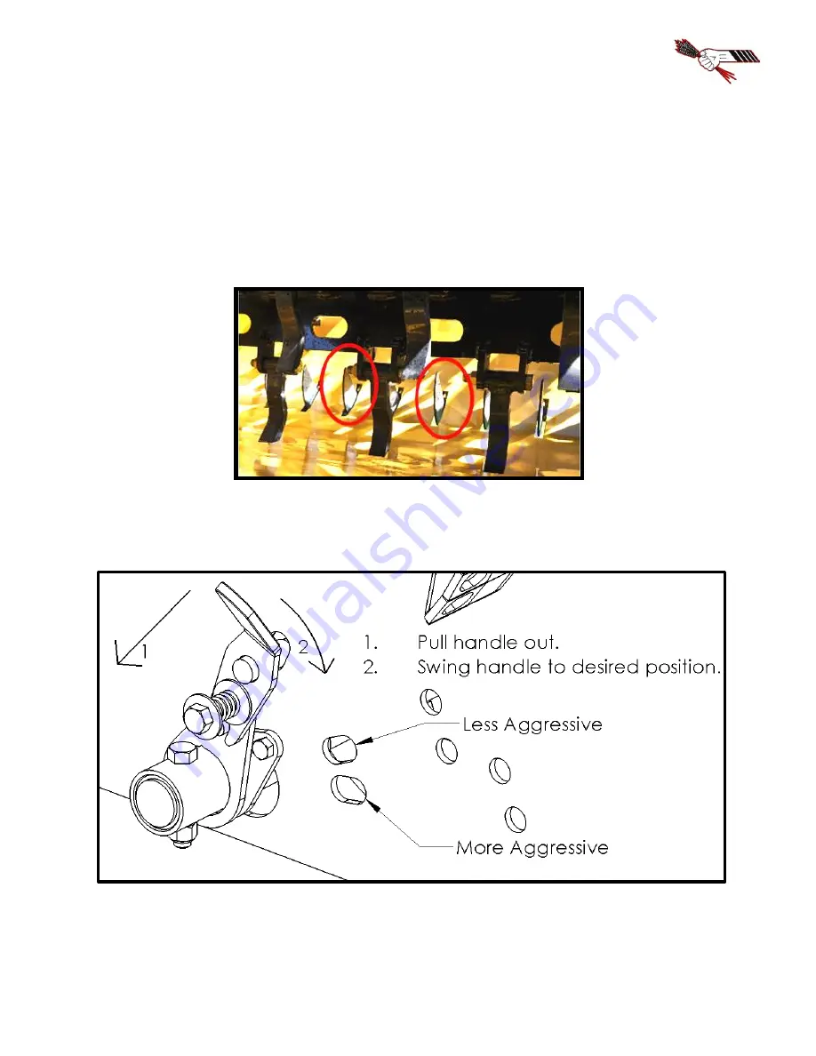
Optional Fine Chop Kit 


The Bale King 5300 processor has an optional fine chop knife kit 

(BMI # 32117) 

available to go 

into the lower tub area.  This option is available if you require a finer cut on the material which 

you are processing such as slough hay and silage bales. 


It is recommended that the knives be lowered when bedding straw as it will affect  your 

spread pattern.  Adjust the machine as needed. 


There  are  two  settings  for  the  fine  chop,  depending  on  how  fine  you  wish  to  cut  the 

material.  These settings achieved by pulling on the handle (towards the back of the machine), then 

selecting the desired hole. 


Summary of Contents for BALE KING 5300 Series

Page 1: ...KING 5300 Bale Processor Operator s Parts Manual Last Updated July 2019 Bridgeview Manufacturing Inc P O Box 4 Gerald Saskatchewan Canada S0A 1B0 Phone 1 306 745 2711 Fax 1 306 745 3364 Email bmi sasktel net www bridgeviewmanufacturing com ...

Page 2: ...Bridgeview Manufacturing Inc ii The Serial Number is located the front tub panel next to the operator manual box Your Authorized Dealer Your Serial Number ...

Page 3: ...on Machine 5300XTR 27 Lubrication and Maintenance 28 Tire Inflation and Rating 30 Twine Removal 31 Gearbox and Flail Replacement Procedure 32 Transportation 34 Trouble shooting Guide 35 Features and Specifications 36 PARTS MANUAL 37 Machine Overview 37 Jack Hitch 38 Wheels Hub 39 Spindle 40 Rotor Drive Components 41 Gearbox 42 PTO Shaft 44 Grates 45 Agitators 46 Rear Tub Components Rear Deflector ...

Page 4: ...view Manufacturing Inc iv TR Kit Option 70 Fine Chop Option 80 Twine Cutter Option 82 Diverter Control Box 83 HYDRAULIC AND ELECTRICAL SCHEMATICS 84 Hose Layout 84 Hydraulics 85 Lights Electrical 98 NOTES 101 ...

Page 5: ...nning operation of your new machine Safety Precautions The following safety precautions MUST be followed to ensure safe operation of the Bale King bale processor ALWAYS turn OFF the tractor when leaving the operating platform DO NOT stand in front of the discharge chute while the machine is running DO NOT walk or move under the bale forks when they are in the upward position unless the cylinder sa...

Page 6: ...he operator must obey all safety labels and must maintain the proper shielding A high percentage of drive line injuries occur when safety shielding is missing or not functioning properly DANGER Contact with a rotating drive line can cause serious injury or death ...

Page 7: ...Bridgeview Manufacturing Inc 3 Discharge DANGER Do not stand on the discharge side of the machine while it is in operation ...

Page 8: ...acturing Inc 4 Rear Fork Lift Area DANGER Stand clear of lift area Do not stand under the forks unless safety locks are installed Deflector Safety Lock Unlock for Operation Lock for Transport and Storage Update picture ...

Page 9: ...the machine using a spline adaptor Use of adaptors will void warranty due to damage caused to the tractor PTO PTO driveshaft or implement DO NOT operate at 540 rpm or use any kind of adaptor to connect to a 540 rpm spline Always ensure that the PTO shaft is attached securely to the tractor When the processor is not hooked to the tractor store the shaft on the PTO holder DO NOT transport the proces...

Page 10: ...ss aggressive or roll the bale more slowly Always ensure that your machine is running at 1000 PTO RPM NOTE Please consult your local dealer to help pinpoint any problems PTO Holder A PTO shaft holder is standard with your new Bale King for safe storage of the PTO shaft when the processor is not in use When unhooking the PTO shaft from the tractor lift the PTO holder to its upright position and res...

Page 11: ...d of the PTO shaft Adjust your tractor accordingly Shielding Be sure that the shielding is not damaged and rotates freely on the drive shaft Working Angles Constant Velocity joints can operate up to 80 degrees for short periods of time Do not operate for long periods on sharp angles Attachment Be sure the drive line is properly attached and all bolts and screws are tight on the implement input sha...

Page 12: ...the shield pop out the red snap then rotate the guard on the bearing to line up the three tabs with the openings and pull it off away from the knuckle joint Remove the nylon bearing from the shaft by spreading it open Shield Assembly Be sure to lubricate the groove in the inner yokes where the shield bearing rides Reinstall shields in the reverse order that they were removed ...

Page 13: ...ntrols Note that the hoses are paired by colour and the following tables show the operation when pushing oil into the hose with the longer marker 5300 3 Remotes Hose Marker Function Long Red Turn agitators clockwise Long Blue Lift rear fork Long Yellow Lift discharge deflector An optional diverter kit BMI 25091 is available to allow the Bale King 5300 to run using only two sets of hoses The functi...

Page 14: ... shafts if the unit is not used for extended periods of time Rusted cylinder shafts are NOT covered by warranty NOTE Check all hoses and fittings periodically for leaks Tighten or replace any dripping components or any worn out hoses Implement Tongue The adjustable hitch on the Bale King features a cast single tongue with hammer strap insert This allows for use with tractors equipped with a hammer...

Page 15: ...ep the load on the forks and cylinders balanced For transport and safety when working under the forks install the red safety locks onto the lift cylinder The Bale King 5300 is equipped with self catching safety locks that do not require a pin to lock in place To install lift the fork all the way up with the hydraulics place the pin catch of the cylinder lock against the top pin and swing into plac...

Page 16: ...is lowered handle moves up Position 6 8 Lowest grate positions most aggressive fastest rate of feed The Bale King should be adjusted according to bale conditions to achieve a rate of feed of approximately 1 5 to 2 minutes Light brittle material such as wheat straw may allow faster processing while tough stringy material such as slough hay green feed or flax will require slower processing Hoop grat...

Page 17: ... a windrow or bunk feeder Swinging the deflector up will allow you to spread straw out over a large area If you also flip the rubber up above right you will be able to fine tune the discharge to control the height and distance To flip the rubber simply pull on the handle and swing into position Then push the handle so that the tabs catch in the notches and lock into place The Bale King 5300 deflec...

Page 18: ...osition Remove the 7 top carriage bolts from the deflector Loosen all the 4 bolts on the front and back of the deflector Raise the deflector to its highest position with the hydraulics Remove the bolts closest to the machine center both front and back and swing the outer deflector down Be sure that the outer deflector fits nicely outside the tub walls Some fine tuning may be required Replace the b...

Page 19: ...is will remove the loose debris preventing spillage from the machine This is especially true when processing soft core bales By reversing direction regularly soft core bales will process more evenly If the tractor has a flow control adjust the oil flow so that the agitators run at a low rate Adjust the flow as needed to find the best speed to process a bale approximately 30 rpm or 12 gpm flow Turn...

Page 20: ...ack straight into the second bale If you are going to a different stack for the second bale only raise the first bale enough to clear the ground Move to the next row and align the machine to the bale before dumping the bale into the tub This gives you good visibility to line up to the second bale Once you have the first bale in the tub and the second bale on the forks raise the bale fork about 1 4...

Page 21: ... s electrical system The diverter kit also features a pilot operated check valve to ensure that the deflector will not fall down due to leaking across the valve A 4 pin plug is used to power the diverter valve on the processor If no power is supplied the hydraulics will still control the rear forks but the deflector will not be functional If the switch in the tractor is activated the deflector can...

Page 22: ...r cut on the material which you are processing such as slough hay and silage bales It is recommended that the knives be lowered when bedding straw as it will affect your spread pattern Adjust the machine as needed There are two settings for the fine chop depending on how fine you wish to cut the material These settings achieved by pulling on the handle towards the back of the machine then selectin...

Page 23: ...l valve allows you to adjust the speed of the augers so that you can meter the grain flow for different situations It is recommended to determine your desired rate based on driving speed and the flow rate of the tractor Setting the valve to 0 will give no grain while setting it to 10 will be full speed The grain tank has the option of running using two three or four sets of hoses Each hose has a c...

Page 24: ...et up Hose Marker Function Long Red Turn agitators clockwise Long Blue Lift rear fork or deflector Long Green Discharge grain 5300TR 2 Remote Set up Hose Marker Function Long Red Turn agitators clockwise Long Blue Lift rear fork or deflector or discharge grain Cleanout doors are located at the bottom end of both the cross auger and the grain tank It is recommended that both be cleaned out at the e...

Page 25: ...hanges the loading process of the bale processor slightly The loading of the second bale involves lifting the bale so the fork and bale are parallel to the ground or just above this point The clamp will be closed around the bale at this point and the fork can be lowered back to the ground The third bale can then be backed under and lifted until it is lightly supporting the second bale After the fi...

Page 26: ...away from the machine slightly when loading 6 If you are loading from the same row you can dump the bale into the machine and back straight into the second bale If you are going to a different stack for the second bale only raise the first bale enough to clear the ground Move to the next row and align the machine to the bale before dumping the bale into the tub This gives you good visibility to li...

Page 27: ...ppropriate location close the clamp fully and then lower the lifting fork 9 Back under the third bale and lift the forks until the third bale is lightly supporting the second bale You will see when to stop lifting as the clamped bale will tilt forward slightly ...

Page 28: ...load the third bale into the tub The 3 Bale Kit also has the option of two three or four sets of hoses Each hose has a coloured marker to identify its function They should be connected at best convenience for the tractor s controls Note that the hoses are paired by colour and the following tables show the operation when pushing oil into the hose with the long marker 5300 3 Bale Kit 4 Remotes Set u...

Page 29: ...that information into a plunger which will trigger two lockout valves one controlling the fork and one controlling the clamp Whichever function is being used at the time of lockout will be locked and will continue to be locked unless the function is backed off from the collision situation If the clamped bale is not being clamped strongly enough before the lockout is triggering the plunger can be a...

Page 30: ...ut cover not shown Once jam nut is loose rotate plunger clockwise to lower counter clockwise to raise depending on your needs Nut is available to move plunger by wrench if necessary otherwise turn by hand on larger radius of plate Once moved to new position retighten jam nut and test hydraulics to confirm proper function ...

Page 31: ...rker 5300 Dual Option Machine 4 Remotes Setup Hose Marker Function Long Red Turn agitators clockwise Long Blue Lift rear fork and deflector Long Yellow Close Clamp Long Green Discharge grain 5300 Dual Option Machine 3 Remotes Setup Hose Marker Function Long Red Turn agitators clockwise Long Blue Lift rear fork and deflector and close clamp Long Green Discharge Grain 5300 Dual Option Machine 2 Remo...

Page 32: ...Bale King bale processor should be done on a regular basis Location Timeline A Hoop Handle 150 Bales or 8 hours whichever comes first B 3 Bale Kit Arm Pivot x2 3 Bale Kit Only C Agitator Bearings x 2 D Rotor Bearing E Bale Fork Pivot x 2 F Wheel Hubs x 2 Seasonally or 300 hours ...

Page 33: ... front of the gear box Apply 3 5 pumps of good quality grease every 8 hours or 150 bales whichever comes first If the gearbox is removed to replace the rotor or perform any other service add 80 pumps of grease to the grease zerk upon reinstallation The gear box requires GL5 80W90 gear oil The oil should be filled to the level plug approximately 500 mL and checked on a regular basis The oil should ...

Page 34: ...nut to closest hole and insert the cotter pin Pack hub full of grease and reinstall the dust cap Proper tire inflation will help to alleviate puncture problems when towing and operating on rough terrain Check for proper tire inflation 24 psi Replace any damaged or worn tires 16Lx16 1 8 ply Check and tighten wheel bolts on a regular basis 125 ft lb Note When inflating tires use a clip on chuck and ...

Page 35: ...tors WARNING Before attempting the removal of twine from the rotor be sure that the machine is stopped and the tractor is shut OFF Place the tractor in park Twines can be removed with the use of the optional knife or any other knife An electric device is also available from suppliers to melt the twine allow it to be pulled off Once melted the twine should be removed immediately to prevent damage t...

Page 36: ...o the tub Orient the gearbox as shown below depending on the processor model Install the breather as shown using teflon tape If necessary re center the rotor in the tub so that the flails are centered between the hoops fine chop slots o Tighten lock collar counter clockwise Apply loc tite to the set screw and torque it to 100 in lb Fill gearbox with oil GL5 80W 90 up to the bottom of the side plug...

Page 37: ...n now be removed by using slight pressure to push it out of the flail Inspect the bolt bushing and the flail for wear If wear is excessive replace with new parts Bridgeview Manufacturing Inc recommends when changing flails to change in PAIRS opposite each other Processing bales with broken flails causes the rotor to be out of balance and excessive vibration may cause machine deterioration ...

Page 38: ...ed tail lights and brake lights Ensure that the supplied SMV Slow Moving Vehicle sign is clearly visible from the rear Lift the forks all the way up and install the safety locks If applicable the 3 Bale Kit should be closed as much as possible without hitting the fork If possible the deflector should be in the folded position Ensure that the deflector safety lock is installed Ensure that the PTO a...

Page 39: ...g machine at less than 1000 PTO RPM Operate machine at rated 1000 PTO RPM Rotor bearing failure Replace failed parts Agitators stopping Excessive loose material in tub causing agitator to jam Reverse direction of bale rotation Turn bale more slowly Tractor relief pressure set too low Set tractor relief pressure to at least 2500 PSI A single agitator stopping Mechanical flow divider valve not funct...

Page 40: ...and Axle Assembly Main Frame 4 x 6 in Tubing Frame Width 52 in Heavy Duty Bale Fork Frame 3 x 6 in Tubing Adjustable Bale Fork Width on centers 48 in or 40 5 in Adjustable Hitch Height 4 settings at 1 5 in intervals Dual Hydraulic Lift Cylinders 3 x 18 x 1 1 2 Rod Single Hydraulic Deflector Cylinder 1 1 2 x 6 x 3 4 Rod Tire Size 16L x 16 1 8 Ply Tire Inflation 24 psi Wheel Nut Torque 125 ft lb Min...

Page 41: ...ANUAL Machine Overview Item Description Item Description 1 Jack Hitch 6 Deflector and Hose Cover 2 Wheels Hub 7 Hose and Manual Holder 3 Inner Tub Components Drive 8 Decals 4 Rear Tub Components 9 Options 5 Rear Forks 10 Diverter Control Box ...

Page 42: ... Hitch Tongue 29785 1 4 Bolt 3 4 x 5 3 4 10802 2 5 Hitch Clevis Kit 29786 1 6 Nut 1 2 Nylon Lock S N 7168 Down Nut 1 Stover Lock S N 7169 Up 10241 21746 1 1 7 Safety Chain 11000lb x 53 21715 1 8 Bolt 1 2 x 2 S N 7168 Down Bolt 1 x 2 S N 7169 Up 10322 18992 1 1 9 Bolt 3 8 x 4 14379 1 10 PTO Cradle 31760 1 11 Nut 3 8 Nylon Lock 10806 1 ...

Page 43: ... NF 10347 16 2 Rim 16 1x14 8 on 8 10354 2 3 Tire 16L 16 1 8 ply See your local tire dealer 2 4 Spindle Assembly See breakdown 29679 2 5 Stover Lock Nut 9 16 21165 2 6 Bolt 3 4 x 2 13800 6 7 Lock Washer 3 4 10284 6 8 Nut 3 4 10283 6 9 Axle Extension TR ONLY 30259 1 10 Bolt 9 16 x 3 5 15575 2 ...

Page 44: ... 2 2 Seal 2 ID 10344 2 3 Inner Bearing Cone 1 3 4 ID 10345 2 4 Inner Bearing Race 10349 2 5 Hub Housing Includes 4 6 10343 2 6 Outer Bearing Race 10346 2 7 Outer Bearing Cone 1 3 8 ID 10348 2 8 Cotter Pin 3 16 x 1 1 2 10072 2 9 Flat Washer 1 1 6 ID x 2 OD 10071 2 10 Castle Nut 1 NF 10153 2 11 Dust Cap 10350 2 ...

Page 45: ...1 7 Bolt 3 8 x 3 4 11816 8 8 Rotor Twine Guard Rear 22413 1 9 Nut 3 8 Serrated Flange 10271 4 10 X Rotor Weldment 22449 1 11 Nut 3 4 Stover Lock 11823 28 12 Brass Flail Bushing 10005 28 13 Rotor Flail 22412 28 14 Bolt 3 4 x 4 3 4 10443 28 17 Bolt 1 2 x 1 1 2 10174 8 18 PTO Shaft See Breakdown 1 19 Gearbox Twine Guard 23002 1 20 Nut 1 2 Serrated Flange 10273 8 21 Gearbox Assembly See Breakdown 1 22...

Page 46: ...Bridgeview Manufacturing Inc 42 Gearbox ...

Page 47: ...12 Relief Plug 3 8 NPT 24015 1 13 Bolt M8 x 25 Gr 8 8 24026 6 14 Lock Washer M8 24016 6 15 O Ring 24017 1 16 O Ring 24018 1 17 Shim 125 x 164 x 0 1 24022 2 18 Shim 125 x 164 x 0 3 24023 2 19 Name Plate Bridgeview 1 20 End Cap 1 21 Seal 60 x 85 x 10 10500 1 22 Shim 68 x 74 5 x 0 1 24024 2 23 Shim 68 x 74 5 x 0 3 24025 2 24 Grease Zerk 1 4 28 Straight 26219 1 25 Bolt M10 x 25 15087 4 26 Lock Washer ...

Page 48: ... Guard Repair Kit Tractor Side 20553 1 8 Guard Assembly Tractor Side 17583 1 9 Guard Assembly Implement Side 17585 1 10 Guard Repair Kit Implement Side 17572 1 11 Yoke Tube Assembly Implement Side 17584 1 12 U joint Cross Bearing Kit 17573 1 13 Shear Assembly Does not come with bolts 14 or 16 29963 1 14 Shear Bolt 3 8 x 2 11817 1 15 Nut 3 8 Stover Lock 17586 1 16 Nut 5 8 Stover Lock 24982 2 17 Bol...

Page 49: ...8 Serrated Flange 10271 6 9 Grate Handle Pivot 31715 1 10 Grease Zerk 1 4 28 x 45 degree 20888 1 11 Bolt 3 8 x 1 13806 6 12 Grate Handle 31725 1 13 Flat Washer 3 8 11667 2 14 Rubber Cover 10297 1 15 S Handle 22187 1 16 Roll Pin 3 16 x 1 1 4 10302 1 17 Grate Handle Spring 10301 1 18 Handle Spring Guide 31711 1 19 Nut 3 4 Nylon Lock 10007 2 20 Grate Shackle 31709 2 21 Grate Shackle Bushing 22415 2 2...

Page 50: ...erk 1 8 NPT Straight 10270 2 5 Agitator Bearing Includes 3 4 10038 2 6 Nut 1 2 Serrated Flange 10273 8 7 Agitator 31596 2 8 Nut 3 8 Serrated Flange 10271 16 9 Agitator Twine Guard 22419 4 10 Bolt 3 8 x 3 4 11816 16 11 Agitator Insert 22084 2 12 Agitator Motor 8 Long Seal Kit 25872 25891 2 13 Lock Washer 1 2 14447 8 14 Socket Head Bolt 1 2 x 3 25952 8 ...

Page 51: ...d 31088 31087 1 1 3 Bolt 1 2 x 1 10824 2 4 Flat Washer 1 2 11668 2 5 Nut 1 2 Serrated Flange 10273 2 6 Bolt 1 4 x 3 4 11809 4 7 Nut 1 4 Serrated Flange 11812 4 8 Nut 3 8 Serrated Flange 10271 2 9 Bolt 3 8 x 1 13806 1 10 Wiring Clamp 13629 2 11 12 Rear Deflector Right Hand Rear Deflector Left Hand 31699 31695 1 1 13 Bolt 3 8 x 3 4 11816 1 14 Wing 31692 1 ...

Page 52: ...ts Wing and Bale Slide DESCRIPTION PART QTY SIDE 1 Bolt 3 8 x 1 13806 9 2 Nut 3 8 Serrated Flange 10271 9 3 Nut 1 2 Serrated Flange 10273 4 4 Wing 31692 1 5 Flat Washer 1 2 11668 4 6 Bolt 1 2 x 1 10824 4 7 Bale Slide 31703 1 8 Flat Washer 3 8 11667 7 ...

Page 53: ...Bridgeview Manufacturing Inc 49 Front Rack DESCRIPTION PART QTY 1 Bolt 1 2 x 1 10824 7 2 Flat Washer 1 2 11668 7 3 Front Rack 31730 1 4 Nut 1 2 Serrated Flange 10273 7 ...

Page 54: ...Bridgeview Manufacturing Inc 50 Rear Forks ...

Page 55: ... 10806 2 5 Grease Zerk 16364 2 6 Cotter Pin 3 16 x 1 1 2 10072 8 7 Cylinder Pin 1 x 4 1 16 22190 2 8 Bushing Insert 1 23708 4 9 Hydraulic Cylinder 3 x 18 x 1 1 2 Seal Kit Stopper Kit 21717 20807 21860 2 10 Cylinder Pin 1 x 3 1 2 10339 2 11 Cylinder Safety Lock 31761 2 12 Cotter Pin 1 4 x 2 10580 2 13 Flat Washer 1 14472 2 14 Fork Tine 22421 2 15 Fork Tine Pin 10031 2 ...

Page 56: ...Bridgeview Manufacturing Inc 52 Deflector Hose Cover S N BK7168 Down ...

Page 57: ...2 1 10 Deflector Pivot 22426 2 11 Inner Deflector 31749 1 12 Bolt 3 8 x 3 4 11816 4 13 Hose Cover 22436 1 14 Cotter Pin 3 16 x 1 1 4 11669 4 15 Cylinder Pin 3 4 x 3 Usable 22007 1 16 Hydraulic Cylinder 1 1 2 x 6 x 3 4 Seal Kit 21711 23738 1 17 Cylinder Pin 3 4 x 3 Usable 22007 1 18 Deflector Rubber Flipper 24463 1 19 Outer Deflector 31754 1 20 Nut 1 2 Serrated Flange 10273 12 21 Bolt 1 2 x 1 10824...

Page 58: ...Bridgeview Manufacturing Inc 54 S N BK7169 Up ...

Page 59: ...24461 1 9 Roll Pin 3 16 x 1 1 4 10302 1 10 Deflector Pivot 22426 2 11 Inner Deflector 32196 1 13 Hose Cover 32191 1 14 Cylinder Pin 3 4 x 3 Usable 22007 1 15 Cotter Pin 3 16 x 1 1 4 11669 4 16 Hydraulic Cylinder 1 1 2 x 6 x 3 4 Seal Kit 21711 23738 1 18 Deflector Rubber Flipper 24463 1 19 Outer Deflector 31754 1 20 Nut 1 2 Serrated Flange 10273 12 21 Bolt 1 2 x 1 10824 8 22 Bolt 1 2 x 2 10322 1 23...

Page 60: ...5 1 3 Bolt 3 8 x 3 4 11816 5 4 Nut 3 8 Serrated Flange 10271 7 5 Nut 1 4 Nylon Lock 11664 4 6 Manual Holder Bracket 31781 1 7 Shear Bolt 3 8 x 2 GRADE 5 10279 4 8 Nut 3 8 Stover Lock 17586 4 9 Flat Washer 3 8 11667 2 10 Bolt 3 8 x 1 13806 2 11 Operator Manual Holder 22409 1 12 Flat Washer 1 4 11666 4 13 Bolt 1 4 x 1 1 4 10240 4 ...

Page 61: ...cluded in the SMV sign kit which are not required DESCRIPTION PART QTY Complete SMV Sign Kit 22411 1 1 Nut 1 4 Serrated Flange 2 2 Galvanized Sign Bracket 1 3 Plastic SMV Sign 1 4 Pan Head Bolt 1 4 x 5 8 2 5 Nut 5 16 2 6 Lock Washer 5 16 2 7 Galvanized Tapered Receiver Bracket 1 8 Carriage Bolt 5 16 x 1 2 2 9 Carriage Bolt 5 16 x 2 10 Lock Washer 1 4 ...

Page 62: ...Bridgeview Manufacturing Inc 58 Hose Holder ...

Page 63: ...0 2 Hydraulic Hose Clamp 1 2 21561 3 Hydraulic Hose Clamp 3 8 22180 4 Hydraulic Hose Clamp 1 4 22181 5 Hydraulic Hose Clamp Cap Large 21725 6 Hydraulic Hose Clamp Cap Small 22182 7 Bolt 5 16 x 3 1 2 13765 8 Bolt 5 16 x 3 22844 9 Bolt 5 16 x 1 3 4 21726 10 Wiring Clamp 13629 11 Bolt 5 16 x 4 1 2 21836 ...

Page 64: ...LE KING 5300 31657 2 2 DANGER PTO 12219 2 3 DANGER Discharge 12230 4 4 DANGER Stand Clear of Lift 12229 1 5 AMC Member 12239 1 6 Hoop Adjustment 31658 1 7 Deflector Safety Lock 22292 1 8 Red Reflector 28383 3 9 Amber Reflector 28384 5 10 TOTAL RATION 24862 1 TR only ...

Page 65: ...Bridgeview Manufacturing Inc 61 3 Bale Kit Option Item Description 1 Left Arm 2 Lockout Mechanism 3 Center 4 Right Arm ...

Page 66: ...Bridgeview Manufacturing Inc 62 Left Arm ...

Page 67: ...erk 16364 1 5 3 Bale Kit Left Arm 31852 1 6 Arm Pin 31660 1 7 Nut 1 2 Nylock 16741 1 8 Nut 1 2 Stover Lock Fine Thread 32153 7 9 Lockout Mechanism SEE DETAIL 1 10 Bolt 1 2 x 1 3 4 Fine Thread 32151 4 11 Bolt 1 2 x 3 1 2 10353 1 12 Bolt 1 2 x 1 1 4 Fine Thread 32152 3 13 Tub Mount 31873 2 14 Nut 3 8 Nylock 10806 1 15 Bolt Shoulder 1 2 x 2 1 4 x 3 8 31358 1 ...

Page 68: ...Bridgeview Manufacturing Inc 64 Lockout Mechanism ...

Page 69: ...806 2 7 3 Bale Kit Lower Spring Guide 31911 1 8 3 Bale Kit Left Mount 31898 1 9 Cotter Pin 21169 1 10 3 Bale Kit Plunger 31925 1 11 Nut 3 8 Serrated Flange 10271 2 12 3 Bale Kit Valve 30980 2 13 Nut 5 16 Serrated Flange 11814 2 14 Nut 3 8 Nylock 10806 1 15 Nut 1 2 Fine Thread 32167 1 16 Clevis Pin 1 2 x 6 31835 1 17 Bolt 5 16 x 3 1 2 30914 1 18 Lynch Pin 13233 1 19 Lockout Door 31928 1 20 Nut 5 16...

Page 70: ...Bridgeview Manufacturing Inc 66 Center ...

Page 71: ...2202 32236 1 2 2 Bolt x 3 27451 2 3 Nut 1 2 Stover Lock Fine Thread 32153 7 4 3 Bale Kit Slider 31892 1 5 Bolt 1 2 x 1 1 4 Fine Thread 32152 4 6 3 Bale Kit Cylinder Mount 31887 1 7 Bolt 1 2 x 1 3 4 Fine Thread 32151 3 8 Cylinder Pin 22291 2 9 Hydraulic Cylinder 30126 1 10 Nut Nylon Lock 15436 2 11 Brass Spacer Bushing 29063 2 ...

Page 72: ...Bridgeview Manufacturing Inc 68 Right Arm ...

Page 73: ...t 1 2 Stover Lock Fine Thread 32153 7 2 Tub Mount 31873 2 3 Bolt 1 2 x 1 1 4 Fine Thread 32152 3 4 3 Bale Kit Right Arm 31854 1 5 Grease Zerk 16364 1 6 Arm Pin 31660 1 7 Nut 1 2 Nylock 16741 1 8 Bolt 1 2 x 1 3 4 Fine Thread 32151 4 9 Bolt 1 2 x 3 1 2 10353 1 ...

Page 74: ...Bridgeview Manufacturing Inc 70 TR Kit Option ...

Page 75: ...Bridgeview Manufacturing Inc 71 TR Kit Option Item Description 1 Tank Front 2 Tank Rear 3 Cross Auger 4 Lid ...

Page 76: ...Bridgeview Manufacturing Inc 72 Tank Front ...

Page 77: ...1 9 Bearing Lock Collar 10367 1 10 Bearing Cover 25117 1 11 Bolt 5 8 x 1 5 10173 5 12 5300 Front Mount Bracket 6200 Front Mount Bracket 30242 30252 1 1 13 5300 Front Mount Strap 6200 Front Mount Strap 30239 30250 1 1 14 Nut 5 8 Stover Lock 20150 2 15 Bolt 1 2 x 1 10824 2 16 Grain Tank Top Strap 30402 2 17 Nut 1 2 Serrated Flange 10273 2 18 Bolt 5 16 x 1 75 21726 1 19 Hydraulic Hose Clamp Cap Large...

Page 78: ...Bridgeview Manufacturing Inc 74 Tank Rear ...

Page 79: ...11812 2 11 Tank Motor WS130 30133 1 12 Nut 1 2 Stover Lock 14393 6 13 Bolt 5 16 x 0 75 20903 4 14 Cross Auger Cleanout Cover 30235 1 15 Nut 5 16 Serrated Flange 11814 5 16 Nut 5 16 Nylock 11815 2 17 Bolt 5 16 x 0 75 Carriage 11662 3 18 Bearing 3 Bolt Pressed Flange Housing 10368 2 19 Bearing 3 4 Includes 20 10366 1 20 Bearing Lock Collar 10367 1 21 Nut 5 8 Stover Lock 20150 5 22 5300 Rear Mount St...

Page 80: ...Bridgeview Manufacturing Inc 76 Cross Auger ...

Page 81: ...0 Nut 1 2 Serrated Flange 10278 8 11 Spout Strap Same P N for both pieces 25122 1 12 Nut 1 4 20891 2 13 Washer 1 4 Flat 14448 2 14 Bolt 1 4 x 3 4 Truss Head 17638 2 15 Cross Auger 30169 1 16 Cross Auger Motor Mount 30194 1 17 Bolt 1 2 x 1 25 10240 6 18 Cross Auger Motor WS080 30132 1 19 Nut 1 2 Stover Lock 14393 6 20 Lock Pin 1 4 x 1 25 13951 1 21 Chain 3 16 x 20 links 25121 1 22 Bolt 3 8 x 2 1027...

Page 82: ...Bridgeview Manufacturing Inc 78 Lid ...

Page 83: ...T QTY 1 Grain Tank Lid 30165 1 2 Bolt 1 2 x 1 50 10174 2 3 Washer 1 2 Fender 10238 2 4 Bushing 1 2 ID x 1 250 OD 10239 2 5 Nut 1 2 Stover Lock 14393 2 6 Nut 5 16 Nylock 11815 3 7 Bolt 3 8 x 5 8 Shoulder 30466 3 8 Lid Upper Support 30163 1 9 Lid Lower Support 30166 1 ...

Page 84: ...Bridgeview Manufacturing Inc 80 Fine Chop Option ...

Page 85: ...2142 1 6 Nut 3 8 Serrated Flange 10271 4 7 Fine Chop Bar 32118 1 8 Nut 1 4 Serrated Flange 11812 26 9 Fine Chop Blade 10404 13 10 Bolt 1 4 x 3 4 11809 26 11 Split Collar 12792 1 12 Fine Chop Front Mount 32122 1 13 Nut 1 2 Nylon Lock 10241 2 14 Fine Chop Pivot 32127 1 15 Bolt 1 2 x 2 3 4 12378 1 16 Flat Washer 1 2 11668 2 17 Bolt 1 2 x 2 1 2 10804 1 18 Compression Spring 21713 1 19 Fine Chop Handle...

Page 86: ...dle Kit 1 2 Twine Cutter Holder Kit 21549 1 3 Rubber Handle Cap 17587 1 4 Twine Cutter Handle 20862 1 5 Bolt 1 4 x 3 4 Truss Head 17638 4 6 Nut 1 4 Serrated Flange 11812 4 7 Twine Cutter Blade 17438 1 8 Twine Cutter Holder Inside Bracket 17690 1 9 Twine Cutter Holder Outside Bracket 17691 1 10 Flat Washer 1 4 11666 2 ...

Page 87: ...mplete Control Box with Cab to Hitch Harness 5300 Series 1 3 Square Plug for Diverter Valve 13657 4 4 pin Trailer Plug 24691 1 5 4 pin Tractor Plug 24690 1 4 5 4 pin Trailer Tractor Plug Kit 25079 1 6 3 way Switch 13561 1 7 Complete Hitch to Valve Harness 5300 Series 24693 1 8 Cover up Sticker for Wing Feed 25125 NOTE 1 plug is needed for each diverter valve NOTE Only used on 5300TR with 3 remote ...

Page 88: ...ear Fork or Lift Discharge Deflector or Discharge Grain 5300X 4 Remote Long Red Turn Agitators Clockwise Long Blue Lift Rear Fork Long Yellow Lift Discharge Deflector Long Green Close Clamp 5300X 3 Remote Long Red Turn Agitators Clockwise Long Blue Lift Rear Fork or Lift Discharge Deflector Long Green Close Clamp 5300X 2 Remote Long Red Turn Agitators Clockwise Long Blue Lift Rear Fork or Lift Dis...

Page 89: ...Bridgeview Manufacturing Inc 85 Hydraulics ...

Page 90: ...Bridgeview Manufacturing Inc 86 ...

Page 91: ...Bridgeview Manufacturing Inc 87 ...

Page 92: ...Bridgeview Manufacturing Inc 88 ...

Page 93: ...Bridgeview Manufacturing Inc 89 ...

Page 94: ...Bridgeview Manufacturing Inc 90 ...

Page 95: ...Bridgeview Manufacturing Inc 91 ...

Page 96: ...Bridgeview Manufacturing Inc 92 ...

Page 97: ...Bridgeview Manufacturing Inc 93 ...

Page 98: ...Bridgeview Manufacturing Inc 94 ...

Page 99: ...k Kit Triple Stack Kit 11743 17977 11789 12895 12897 HH Pilot operated Check Valve 19114 II Check Valve 8MJ 8FB 12171 JJ Pioneer Tip 8FB 17379 KK Hose Marker Long Red 20790 LL Hose Marker Short Red 18140 MM Hose Marker Long Blue 18497 NN Hose Marker Short Blue 18141 OO Hose Marker Long Yellow 16520 PP Hose Marker Short Yellow 16521 QQ Hose Marker Long Green 16522 RR Hose Marker Short Green 17053 S...

Page 100: ... 6MJ90 10200 I Adaptor 8MB 4MJ 22160 J Adaptor 8MJ90BH 10531 K Adaptor 8MJ45BH 22189 L Adaptor 8FJXR 8MJT 11768 M Adaptor 6MBR 6MJT 23726 N Adaptor 6MB 6MJ 10162 O Adaptor 6MB 6MJ90 10201 P Adaptor 6MJ90BH 10187 Q Adaptor 6MJ 6FJX90 12162 R Adaptor 6MB 6MJ Orifice 1 32 17436 S Adaptor 8MJBH 28774 T Adaptor 12MB 8MJ 25937 U Adaptor 6MJBH 11767 V Adaptor 8MB Plug 31013 W Adaptor 12MB 8MJ90 22174 NOT...

Page 101: ...19 3 8 13 5 OAL 6FJX 6FJX 20 3 8 11 25 OAL 6FJX 6FJX90 21 3 8 9 25 OAL 6FJX 6FJX 22 3 8 8 75 OAL 6FJX 6FJX 23 1 4 128 OAL 4FJX 6FJX90 24 1 4 35 OAL 6FJX 6FJX90 25 1 4 26 OAL 6FJX 6FJX90 26 1 4 20 25 OAL 6FJX 6FJX90 27 1 4 16 25 OAL 6FJX 6FJX90 28 1 4 13 5 OAL 6FJX 6FJX 29 1 4 12 25 OAL 6FJX 6FJX90 30 3 8 8 5 OAL 6FJX 6FJX 31 1 2 81 OAL 8FJX 8FJX 32 1 2 125 OAL 8MB 8FJX 33 3 8 78 OAL 6FJX 8FJX 34 3...

Page 102: ...Bridgeview Manufacturing Inc 98 Lights Electrical Diverter Controls ...

Page 103: ...Bridgeview Manufacturing Inc 99 ...

Page 104: ...Bridgeview Manufacturing Inc 100 Lights ...

Page 105: ...Bridgeview Manufacturing Inc 101 NOTES ...

Reviews: