background image

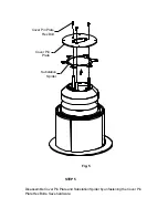
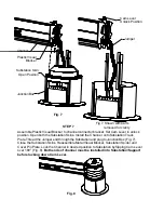
Cover Pin

Plate

Cover Pin Plate

Hex Bolt

Substation

Spider

STEP 5

Disassemble Cover Pin Plate and Substation Spider by unfastening the Cover Pin
Plate Hex Bolts. Save hardware.

Fig. 5

Summary of Contents for M-SUB

Page 1: ...SUBSTATION AND CHANNEL MODEL Assembly Instructions TOOLS REQUIRED 1 2 WRENCH PHILIPS SCREWDRIVER 3 8 WRENCH ELECTRIC HAND DRILL LIQUID WORKSPACE M SUB...

Page 2: ...kirt Remove Substation Top Cover by pulling it up Disassemble Substation Track Plate and Substation Skins by removing three Substation Track Plate screws Fig 1 Save hardware for reassembly Substation...

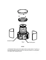
Page 3: ...bstation Skirt up and hold it in place with two wooden blocks 7 long Fig 2 Mark bolt hole pattern 3 holes on the floor using hole locations in mounting plate as template Move Substation aside Wooden B...

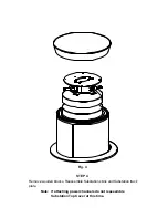
Page 4: ...2 concrete expansion anchor Drill holes and complete installation using hardware manufacturer s recommended proce dure b For wood floor Drill appropriate holes depending on type of wood for 1 4 x 2 la...

Page 5: ...STEP 4 Remove wooden blocks Reassemble Substation skins and Substation track plate Fig 4 Note If attaching power channels do not reassemble Substation Top Cover at this time...

Page 6: ...Cover Pin Plate Cover Pin Plate Hex Bolt Substation Spider STEP 5 Disassemble Cover Pin Plate and Substation Spider by unfastening the Cover Pin Plate Hex Bolts Save hardware Fig 5...

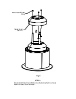
Page 7: ...Metal Visual Blocker Metal Visual Blocker Screw STEP 6 Disassemble Metal Visual Blocker by unfastening the three Visual Blocker Screws Save hardware Fig 6...

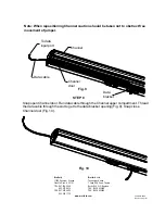
Page 8: ...Substation Skins Install the Channel onto Substation Track Plate Thread the Jumper end through the Substation and plug to Junction Box Fig 7 Close the Substation Skins Reassemble Metal Visual Blocker...

Page 9: ...opening Fig 9 Snap close Channel door Fig 10 Fig 10 Part 031 6464 Rev 07 15 03 IM Bretford Bretford Ltd 11000 Seymour Avenue Technology House Franklin Park IL 60131 7 Lake End Court Taplow TEL 847 67...

Reviews: