background image


11 

5  INSTALLATION AND  COMMISSIONING 

5.1 

Unpacking 

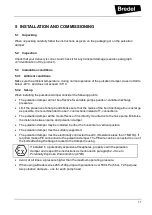
When unpacking carefully follow the instructions as given on the packaging or on the pulsation 
damper. 

5.2 

Inspection 

Check that your delivery is correct and check it for any transport damage (see also paragraph 

4.1 Identification of the product

). 

5.3 

Installation conditions 

5.3.1  Ambient conditions 

Make sure the ambient temperature, during normal operation of the pulsation damper, does not fall to 
below -20°C, and does not 45°C. 

5.3.2  Set-up 

When installing the pulsation damper consider the following points:  


The pulsation damper will not be effective for variable pump speeds or variable di scharge 
pressures. 


Limit the presence of sharp bends. Make sure that the radius of the bent discharge line is as large 
as possible. It is recommended to use Y-connections instead of T-connections. 


The pulsation damper will be most effective if it is directly mounted onto the hose pump. Minimise 
the distance between pump and pulsation damper. 


The pulsation damper may be installed in either the horizontal or vertical position.  


The pulsation damper must be suitably supported. 


The pulsation damper must be electrically connected to earth. (Resistance less than 1 MOhm). If 
required make a PE connection to the pulsation damper. The PE wire can be connected to one of 
the bolts attaching the flange bracket to the damper housing.  


If installed in a potentially explosive atmospheres, properly earth the pulsation 
damper and respect the instructions as mentioned in paragrap

2.4 Use In 

Potentially Explosive Environments (ATEX)


Avoid, at all times, a pressure higher than the maximum operating pressure.  


When using a Bredel series 265-2100 pump with pulsations over 500 kPa (5 bar, 72.5 psi) use 
two pulsation dampers - one for each pump head. 

Summary of Contents for PD/100

Page 1: ...Pulsation damper series PD 40 PD 65 and PD 100 Manual ORIGINAL INSTRUCTIONS...

Page 2: ...plies to all damage inclusive of without limitation compensating direct indirector consequential damage loss of data income or profit loss or damage to possessions and claims of third parties Watson M...

Page 3: ...4 Pulsation damper selection 10 5 INSTALLATION AND COMMISSIONING 11 5 1 Unpacking 11 5 2 Inspection 11 5 3 Installation conditions 11 5 3 1 Ambient conditions 11 5 3 2 Set up 11 5 4 Lifting and moving...

Page 4: ...ents installation maintenance or repair jobs which fall beyond the scope of this manual contact your Bredel representative Make sure you have the following information at hand serial number pulsation...

Page 5: ...rm resulting from this The pulsation damper is designed in conformance with the current European standards and directives Only use the pulsation damper in conformance with the intended use described a...

Page 6: ...any responsibility for damage or harm caused by not strictly observing the safety regulations and instructions in this manual or by negligence during installation use maintenance and repair of the pul...

Page 7: ...his manual The safety form must be applied to the outside of the shipping carton Parts which have been contaminated or which have been corroded by chemicals or other substances which can pose a health...

Page 8: ...diameter C Type of material of inner liner D Maximum permissible working pressure E Production code 4 2 Operation of the pulsation damper The Bredel pulsation damper reduces the pulses created in the...

Page 9: ...o be pumped Dependent on the specific requirements of your application a matching hose should be selected A Outer extruded layer made of natural rubber B Four nylon reinforcement layers C Inner extrud...

Page 10: ...your hose pump Selection table pump and pulsation damper Pulsation damper type Pump type PD 40 Bredel 25 Bredel 32 Bredel 40 PD 65 Bredel 50 Bredel 65 PD 100 Bredel 80 Bredel 100 If you are in doubt a...

Page 11: ...commended to use Y connections instead of T connections The pulsation damper will be most effective if it is directly mounted onto the hose pump Minimise the distance between pump and pulsation damper...

Page 12: ...onsfor lifting movements are adhered to and that the lifting is carried out by qualified personnel only 5 5 Setting the pulsation damper pressure level for operation The pulsation damper air or nitrog...

Page 13: ...v inside the vessel 6 Pressurize the vessel to approximately 80 of the actual fluid discharge pressure of the hose pump p2 close to the pulsation damper 7 Continue to fill the vessel with gas and clos...

Page 14: ...ump back on ensure that all valves present in the pipe work are opened 6 1 Cleaning the pulsation damper hose internally The inside of the pulsation damper hose is easily cleaned by flushing the pump...

Page 15: ...d used hose 1 Check all parts to be installed for any damage and replace when necessary 2 Grease all metal parts which are not corrosion protected and O rings with Molykote 55M or equivalent 3 Place o...

Page 16: ...nstalling an additional flange on both sides of the pulsation damper flangesand external gas pressure up to 1600 kPa 16 bar 232 psi above atmospheric can be applied 6 4 Checking the Pressure relief va...

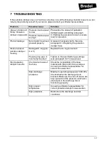
Page 17: ...ose Pressure loss at pulsation damper housing Damaged O ring pos 4 or 5 Replace the O ring concerned Pressing ring pos 7 incorrectly mounted Tighten to the specified torque settings see paragraph 8 2...

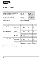
Page 18: ...n Unit PD 40 PD 65 PD 100 Pressing ring pos 7 Thread M115 x 2 M145 x 2 M185 x 3 Torque value N A N A N A Toolbar diameter mm 16 16 16 inch 0 63 0 63 0 63 Hose clamp pos 8 Thread M8 M8 M10 Torque value...

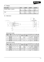
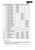
Page 19: ...redel 65 20 6 3 65 8 145 185 PD 100 Bredel 80 100 324 1356 1295 20 8 8 48 175 80 8 160 200 18 Bredel 100 22 3 100 180 220 Dimensions in inch Damper Type Pump Type A B C D E F G K1 K2 n L M N Steel SS...

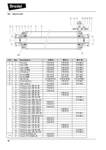
Page 20: ...32 P040293 2 Flange steel EN 40 40 P040209 2 Flange steel EN 65 50 P065213 2 Flange steel EN 65 65 P065209 2 Flange steel EN 80 100 P100213 2 Flange steel EN100 100 P100209 2 Flange steel ASA 40 25 P...

Page 21: ...Insert PVC PD 100 100 P100212 2 Insert PP PD 100 100 P100292 2 Insert PVDF 100 100 P100282 11 8 Bolt M8 x 20 F111071 8 Bolt M10 x 25 F111096 8 Bolt M12 x 30 F111130 12 8 Washer M8 Spring Lock F336011...

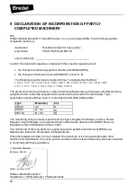
Page 22: ...group I dangerousfluids and were subjected to the conformity assessment procedure as mentioned in the table below Type examination module B has been in conformity with AD 2000 Edition 2002 Type Modul...

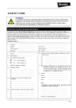
Page 23: ...f the packaging containing the item s The sender of the item s is responsible for cleaning and decontaminating of the item s before returning them in such w ay that it is safe for the receiver to open...

Page 24: ...978 658 0041 E mail support wmftg us Internet www wmftg com Other areas Watson MarlowBredel B V P O Box 47 NL 7490 AA Delden The Netherlands Phone 31 74 3770000 Fax 31 74 3761175 E Mail bredel wmftg...

Reviews: