background image

DESCRIPTION

14

4

DESCRIPTION

4.1

Identification of the product

4.1.1

Identification of the product

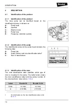
The hose pump can be identified based on the
identification plates or stickers on:

A:

Pump head

B:

Gearbox

C:

Electric motor

D:

Pump hose

E:

Frequency controller (option)

4.1.2

Identification of the pump

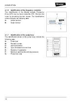
The identification plate on the pump head contains the
following data:

A:

Pump type

B:

Serial number and rotor identification letter

1

C:

Year of manufacture

4.1.3

Identification of the rotor

The rotor identification letter identifies which type of
rotor is mounted to the pump. The table below shows
the rotor identification letter and the article number of
the mounted rotor. Also refer to 

11.5.3

.

1

For information on the rotor identification letter, refer 
to 

4.1.3

.

Letter

Bredel 10

Bredel 15-20

blank

no rotor

no rotor

A

210103L

215103L

Summary of Contents for Hose pump Series

Page 1: ...screen 4 Select the required language click 1x with the left mouse button The PDF reader program will automatically start and the required user manual appears on screen Shortcuts In the left margin yo...

Page 2: ...2...

Page 3: ...3 Hose pump series Bredel 10 Bredel 15 and Bredel 20 Manual...

Page 4: ...s to all damage inclusive of without limitation compensating direct indirect or consequential damage loss of data income or profit loss or damage to possessions and claims of third parties Watson Marl...

Page 5: ...TION 4 1 Identification of the product 14 4 1 1 Identification of the product 14 4 1 2 Identification of the pump 14 4 1 3 Identification of the rotor 14 4 1 4 Identification of the gearbox 15 4 1 5 I...

Page 6: ...8 7 3 Additional maintenance in potentially explosive environments 30 7 4 Cleaning the pump hose 30 7 5 Changing lubricant 31 7 6 Replacing pump hose 31 7 6 1 Removing pump hose 31 7 6 2 Cleaning the...

Page 7: ...Gearbox 52 11 3 Electric motor 53 11 4 Variable Frequency Drive VFD optional 53 11 5 Parts list 54 11 5 1 Overview 54 11 5 2 Cover assembly 55 11 5 3 Pump head assembly 56 11 5 4 Support assembly 57 1...

Page 8: ...e frequency controller is not included in this manual However if additional documentation is supplied you must follow the instructions in this additional documentation 1 4 Service and support For info...

Page 9: ...our local government about the possibilities for reuse or environment friendly processing of packaging materials contaminated lubricant and oil CAUTION Always observe the local rules and regula tions...

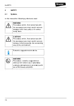
Page 10: ...the hose pump or in serious bodily harm CAUTION Procedures which if not carried out with the necessary care may result in serious damage to the hose pump the surrounding area or the environment Remar...

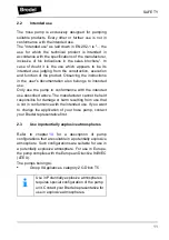
Page 11: ...conformance with the intended use described above The manufacturer cannot be held responsible for damage or harm resulting from use that is not in conformance with the intended use If you want to chan...

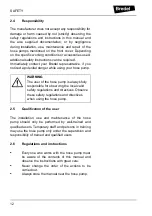
Page 12: ...pump 2 5 Qualification of the user The installation use and maintenance of the hose pump should only be performed by well trained and qualified users Temporary staff and persons in training may use t...

Page 13: ...rm as present in the back of this manual The safety form must be applied to the outside of the shipping carton Parts which have been contaminated or which have been corroded by chemicals or other subs...

Page 14: ...plate on the pump head contains the following data A Pump type B Serial number and rotor identification letter1 C Year of manufacture 4 1 3 Identification of the rotor The rotor identification letter...

Page 15: ...duction ratio E Number of revolutions per minute 4 1 5 Identification of the electric motor The identification plate on the electric motor contains the following data A Type number B Serial number C A...

Page 16: ...ing the two screws The identification sticker contains the following data A Article number B Serial number 4 1 7 Identification of the pump hose The identification sticker on the pump hose contains th...

Page 17: ...upport F Gearbox G Electric motor H Frequency controller 4 3 Operation of the pump The heart of the pump head consists of a specially constructed pump hose A which lies contorted against the inside of...

Page 18: ...ial In phase 2 the product is drawn into the hose by the continuous turning motion of the rotor In phase 3 the second integral pressing shoe will subsequently compress the pump hose Due to the continu...

Page 19: ...the hose type Each hose type is marked by a unique colour code The Bredel pump hoses have been carefully machined therefore there are minimum tolerances in wall thickness It is very important to guar...

Page 20: ...entative 4 4 3 Lubrication and cooling The pumphead in which the rotor and pump hose can be found is filled with Bredel Genuine Hose Lubricant This lubricant lubricates the movement between the hose a...

Page 21: ...ter 10 4 7 Frequency controller Refer to the also supplied documentation of the supplier and 11 4 If the pump is to be used in potentially explosive atmospheres refer to chapter 10 4 8 Available optio...

Page 22: ...The pump materials and protective layers are suitable for indoor set up and a protected outdoor set up Under certain conditions the pump is suitable for limited outdoor set up or a salty or aggressive...

Page 23: ...th as flexible hose in the suction or discharge line This avoids the need to remove the connection lines when changing a pump hose Keep the delivery and suction lines as short and direct as possible S...

Page 24: ...lure is removed the motor can restart automatically The automatic restart can be dangerous in certain pump installations All control cables outside the enclosure must be shielded and have a cross sect...

Page 25: ...lifted using the lifting eye plus additional support using suitably rated straps or slings A For the weights refer to 11 1 5 5 5 Placing the pump Position the pump on a horizontal surface Use suitabl...

Page 26: ...uine Hose Lubricant via the breather plug See also 7 5 6 2 Commissioning 1 Connect the pipework 2 Make sure that there are no obstructions such as closed valves 3 Switch on the hose pump 4 Check the r...

Page 27: ...ication follow the instructions in chapter 9 or consult your Bredel representative 6 Check the capacity range of the frequency controller In case of any deviations consult the documentation of the sup...

Page 28: ...Disconnect and lock the power supply to the pump drive before any work is carried out In case the motor is fitted with a frequency controller and has a single phase power supply wait two minutes to m...

Page 29: ...for any leakage Before startup of the pump and on a sched uled interval during oper ation In case of leakage con sult your Bredel repre sentative 4 Check pump for deviat ing temperature or strange noi...

Page 30: ...water check if the hose liner material is resistant to it Also check if the pump hose can resist the cleaning temperature Special cleaning balls are also available Contact your Bredel representative f...

Page 31: ...ver For this purpose remove the breather cap B and position a funnel C in the breather Pour the lubricant in the pump housing via the funnel 3 Keep on pouring until the lubricant level has risen above...

Page 32: ...and tighten it firmly 4 Disconnect the suction and discharge lines 5 Loosen hose clamp A of both the inlet and outlet ports by loosening bolt B 6 Loosen the retaining bolts A of the bracket B and rem...

Page 33: ...or if necessary Also see the maintenance scheme in 7 2 6 Replace the cover and fasten the retaining bolts with the correct torque Refer to 11 1 6 7 Switch on the electrical supply to the pump 7 6 3 Fi...

Page 34: ...heck that the hose clamps B are not damaged and replace them if necessary 6 First fit the inlet port Slide the rubber bush D over the hose Push the bracket A and the hose clamp B over the hose togethe...

Page 35: ...port proceed in the same way as described above for the inlet port 10 Fill the pump housing with Bredel Genuine Hose Lubricant Refer to 7 5 11 Connect the suction and discharge lines 7 7 Exchanging re...

Page 36: ...de enough for the rotor to fall 6 Remove the nuts B the washers C and the pump drive A 7 Put a plastic or wooden drive pin A on the rotor 8 Hit the drive pin firmly with a hammer to remove the rotor 9...

Page 37: ...ew seal ring A using good engineering practises The seal ring must be fitted in the correct orientation B Make sure that the open side points to the pump cover 14 Slightly oil the inner ring of the ne...

Page 38: ...C Tighten to the specified torque settings Refer to 11 1 6 19 Put the hose pump upright on the support 20 Check the position of the rotor If necessary press the rotor on the hub until it clicks on the...

Page 39: ...the high level float switch to the auxiliary power circuit via the 2 metre long PVC cable 2 x 0 34 mm2 Bear in mind that the electrical contact of the float switch is normally closed NC The knob is up...

Page 40: ...e 2 meter long PVC cable 3 x 0 34 mm2 Adjustment sensor The sensor A must be adjusted at an offset of 0 75 1 25 mm to the rotor B Where the float switch is constructed to stop the equipment operating...

Page 41: ...on of untreated parts For this purpose use the correct protection or packaging After a long period of standstill or storage the static load on the pump hose may have caused permanent deformation which...

Page 42: ...roller and has a single phase power supply wait two minutes to make sure that the capacitors have discharged Problem Possible cause Correction Failure to operate No voltage Check that the supply power...

Page 43: ...o high Consult the Bredel repre sentative about the maxi mum temperature range of the product Internal friction on the hose caused by blocked or poor suction characteristics Check pipework valves for...

Page 44: ...blockages and that sufficient product is available Connections and hose clamps not correctly mounted which makes the pump suck air Tighten connections and hose clamps The filling degree of the pump ho...

Page 45: ...atibility of the hose material with the product to be pumped Consult your Bredel repre sentative for correct hose selection High pump speed Reduce pump speed High discharge pressures The hose life is...

Page 46: ...the inlet pressure Lubricant leakage at bracket Hose blocked by an incom pressible object in the hose The hose cannot be compressed and will be pulled into the pump hous ing Remove hose check for bloc...

Page 47: ...ead on one of the ports The plate contains the following data A ATEX code B ATEX document number C year of manufacture The following table explains the ATEX code on the ATEX plate II Group II equipmen...

Page 48: ...o meet your requirements concerning ATEX Please contact your Bredel representative 10 2 4 Frequency controller The frequency controller must be selected to meet your requirements concerning ATEX Pleas...

Page 49: ...f operation 0 16 0 60 1 09 Capacity per revolution l rev 0 022 0 083 0 152 Permissible ambient temperature C 20 to 45 Permissible product temperature C 10 to 80 Sound level at 1 m dB A 60 Maximum work...

Page 50: ...s Description Material 1 Pump housing Cast iron 2 Cover Cast iron 3 Pump rotor Cast iron 4 Pump support Galvanised steel AISI 316 optional 5 Bracket AISI 316 6 Fasteners AISI 316 7 Seals gaskets NBR 8...

Page 51: ...t is registered at NSF NSF Registration No 123204 Category Code H1 See also www NSF org USDA 11 1 5 Weights Bredel 10 Bredel 15 20 Lubricant Bredel Genuine Hose Lubricant Bredel Genuine Hose Lubricant...

Page 52: ...rbox Pos Description Torques Nm Bredel 10 Bredel 15 20 A Cover 10 25 B Hose clamp 3 3 C Bracket 10 25 D Support 10 10 E Inspection window 1 5 1 5 Type Co axial gearbox with helical gears Number of sta...

Page 53: ...ible dimension is achieved Optional motor adapter Adapters in conformance with IEC B5 or NEMA TC In case of doubt about the local applicable regulations for the drive connec tion contact your Bredel r...

Page 54: ...ly Refer to 11 5 2 2 Pump head assembly Refer to 11 5 3 3 Pump support assembly Refer to 11 5 4 4 Barbed nipple assembly Refer to 11 5 5 5 Threaded nipple assembly Refer to 11 5 6 6 Flange assembly 1...

Page 55: ...23010 4 F523012 F523012 4 1 Drain plug F911502 F911502 F911502 5 1 Gasket F342019 F342019 F342019 6 1 Inspection window 210155 215155 215155 7 1 Gasket 210156 215156 215156 8 3 Round head screw F55253...

Page 56: ...housing 210101 215101 215101 3 1 Gasket 210123 215123 215123 4 1 Rotor low pressure 210103L 215103L 220103L Rotor medium pressure 210103H 215103H 220103H Rotor high pressure 210103X 215103X 220103X 5...

Page 57: ...25 x 63 mm 29064255 29064255 29064255 Coupling 25 x 68 mm 29069255 29069255 29069255 Pos Qty Description Bredel 10 Bredel 15 Bredel 20 1 1 Pump support 210106 215106 215106 2 4 Nut hex head F516010 F5...

Page 58: ...Bredel 20 1 2 Rubber bush 210119 215119 215119 2 2 Hose clamp C112507 C112508 C112508 3 2 Barbed nipple PTFE 210688010 215688015 215688020 Barbed nipple PVDF 210690010 215690015 215690020 4 2 Bracket...

Page 59: ...197 215197 215197 4 4 Bolt Hex head F504036 F504054 F504054 5 4 Washer F532008 F532009 F532009 6 2 Threaded nipple BSP SS 210693010 215693015 215693020 Barbed nipple SS 210686010 215686015 215686020 T...

Page 60: ...5119 2 2 Hose clamp C112507 C112508 C112508 3 2 Bracket 210197 215197 215197 4 4 Bolt Hex head F504036 F504054 F504054 5 4 Washer F532008 F532009 F532009 6 2 Threaded nipple BSP SS 210693010 215693015...

Page 61: ...5 Bredel 20 1 2 Rubber bush 210119 215119 215119 2 2 Hose clamp C112507 C112508 C112508 3 2 Flange bracket 210197A 215197A 215197A 4 4 Bolt Hex head F504036 F504054 F504054 5 4 Washer F532008 F532009...

Page 62: ...cription Bredel 10 Bredel 15 Bredel 20 1 1 Pump housing 210101A 215101A 215101A 2 1 Revolution counter 29060367 29060367 29060367 3 1 Gasket ring F724009 F724009 F724009 Pos Qty Description Bredel 10...

Page 63: ...s of Directive 2006 42 EC Peristaltic hose pump Bredel 10 20 series for the transportation of various kinds of fluids In addition the machinery complies with the harmonised standard s other standards...

Page 64: ...separate Decontamination Certificate for each item returned RGA KBR no 1 Company Address Telephone Postal code Fax number 2 Product 3 4 Cleaning fluid to be used if residue of chemical is found durin...

Page 65: ...NOTES 65 Notes NOTES...

Page 66: ...NOTES 66...

Page 67: ...NOTES 67...

Page 68: ...9 TS04 026 C Watson Marlow Bredel B V P O Box 47 NL 7490 AA Delden The Netherlands Telephone 31 0 74 3770000 Fax 31 0 74 3761175 E mail bredel wmpg com Internet http www bredel com 2013 Watson Marlow...

Reviews: