background image


 USER MANUAL 


12 


2.


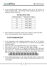
In  the  working  mode  setting  interface,  click  “

”  or  “

”  button  to 

select  working  mode,    the  working  mode  changing  sequence  is  as 
following: 00-01-02-03-04 


Working Mode Table


Working Mode 

Temperature range 

00 

100

-350


01 

100

-400


02 

100

-450


03 

100

-500


04 

100

-550


3.


After selecting the working mode, click 

 button to save and then 

return to the parameter menu selecting interface. 


2.5.5 Password Set 


1.


In the parameter menu selecting interface, click “

” or “

” button 

to select the menu “-4-”, and then click “*” button into the password 
setting interface. 

2.


Once  into  the  new  password  setting,  the  LCD  displays  “---”.  After 

that, click the “

” or “

” button, the 100’s digit is bright. 

3.


At the time, click the “

” or “

” button to select the 100’s digit, and 

then click the “*” button when displaying the selected value of 100’s 
digit. After that it comes into 10’s digit set. The setting methods of 
the 10’s digit and 1’s digit are same with the 100’s digit. 

1

2

3

4

5

6

7

8

9

0


4.


If the setting passwords are not same with each other, it will return 
to the work state directly, which means the password setting is not 
successfully.  

Summary of Contents for Quick Tools QU3205

Page 1: ...BEDIENUNGSANLEITUNG QU3205 L tstation 150W Soldering Station Br unlich GmbH Am Heideberg 26 D 06886 Lutherstadt Wittenberg Tel 49 0 3491 6181 0 Fax 49 0 3491 6181 18 e mail info quick tools de www qui...

Page 2: ...atur kalibrieren 10 1 7 L tspitze 11 1 8 Fehlermeldungen 14 1 9 L tkolben und Heizelement 14 1 10 Verf gbare L tspitzen 16 2 English 1 2 1 Safety Instruction 1 2 2 Characteristics 3 2 3 Specification...

Page 3: ...halten ACHTUNG Dessen Nichtbeachtung kann m glicherweise zur Verletzung des Benutzers oder zu einer Besch digung beteiligter Objekte f hren Zu Ihrer eigenen Sicherheit sollten Sie diese Hinweise einha...

Page 4: ...Sie diese giftigen D mpfe oder Gase nicht ein und sorgen Sie f r ausreichende Bel ftung Tragen Sie Schutzkleidung Schutzhandschuhe Schutzbrille etc und verhindern Sie den Kontakt des L tkolbens mit H...

Page 5: ...n durch den Kundendienst ersetzt werden um m gliche Gef hrdungen wie elektrische Schl ge Kurzschl sse oder Br nde zu verhindern Das Ger t ist nur mit der auf dem Ger t angegebenen Nennspannung und Fre...

Page 6: ...smodi L tkolben mit 1 2m flexiblem Silikonanschlusskabel 1 3 Technischen Daten Anzeige LCD IST SOLL Temperatur Nennleistung 150 Watt Betriebs Spannung 230 Volt 50 Hz Arbeits Temperaturbereich 100 550...

Page 7: ...ach Sicherungsring leicht eindrehen 4 Stecken Sie den Netzstecker in eine Schutzkontakt Steckdose 5 Schalten Sie die L tstation ein HINWEIS Platzieren Sie den L tkolben immer im L tkolbenst nder wenn...

Page 8: ...ede der 3 Festtemperaturen durch 1 4 3 Signalton Ein Ausschalten Dr cken Sie im eingeschalteten Zustand die Tasten gleichzeitig f r 3 Sekunden Im Display wird der Ton Status durch ein Symbol angezeigt...

Page 9: ...sch eingegeben wird schaltet die Station in den Arbeitsmodus zur ck Standard Passwort 000 1 Die Station muss sich im Eingabemodus befinden es wird angezeigt 2 Das Passwort kann mit den Tasten eingegeb...

Page 10: ...1 Funktion 2 ausw hlen und diese mit best tigen Im Auslieferungszustand wird der Wert 20 angezeigt 2 Mit den Tasten kann der Wert im Bereich von 01 99 Minuten ge ndert werden Wenn die Standby Funktio...

Page 11: ...te best tigt die Eingabe danach erfolgt die Eingabe der 10er und der 1er Stelle Taste best tigt und fragt zur Kontrolle erneut das Passwort ab Erneut die Taste f hrt dann zur Speicherung des neuen Pas...

Page 12: ...n Anzeige im Display IST Temperatur identisch der eingestellten SOLL Temperatur ist messen Sie diese an der Spitze mit dem Temperatur Messger t Hinweise des Messger tes beachten Halten Sie die 3 Taste...

Page 13: ...b W hlen Sie eine Spitze die schnell und effektiv die notwendige W rme bertragen kann je kleiner der Spitzendurchmesser desto schlechter wird die W rme in die L tstelle bef rdert c Mit einer kurzen Sp...

Page 14: ...L tspitze ausreichend belotet abgelegt werden und die Spitzentemperatur abgesenkt oder die Station ausgeschaltet werden Dieses reduziert die Oxidationsbildung 7 3 L tspitzenpflege ACHTUNG Niemals mit...

Page 15: ...neu aktiviert werden Es befinden sich Verunreinigungen im Lot Der Lotdraht enth lt kein passendes Flussmittel 4 L tspitze reaktivieren Benutzen Sie zur RE Aktivierung der L tspitze einen TIP Aktivator...

Page 16: ...element auf Raumtemperatur abk hlen und ziehen Sie den Stecker des L tkolbens aus der L tstation Messen Sie den Widerstand zwischen den Anschl ssen wie in der Tabelle angegeben Wenn Sie einen abweiche...

Page 17: ...tkolben e L sen Sie die berwurfmutter nipple of tip vom L tkolben f Ziehen Sie das Heizelement PCB und Kabel in Richtung Spitze aus dem Griff HINWEIS Benutzen Sie keine Metall Werkzeuge um die Spitze...

Page 18: ...BEDIENUNGSANLEITUNG 16 1 10 Verf gbare L tspitzen...

Page 19: ...en viel Freude und Erfolg beim Einsatz Ihrer QUICK L tstation und sind gern an Ihren Anregungen f r Verbesserungen interessiert Kontaktieren Sie uns auch bei auftretenden Problemen oder Fragen zu Ihre...

Page 20: ...e lich deren zum Zeitpunkt der Erkl rung geltenden nderungen entspricht Folgende harmonisierte Normen wurden angewandt RICHTLINIE DES EUROP ISCHEN PARLAMENTS UND DES RATES zur Harmonisierung der Recht...

Page 21: ...the task at hand When the unit is turned on the soldering tip automatically heats up to the last set temperature There is a risk of burns on the surfaces The device is designed for brazing soft solder...

Page 22: ...Otherwise short circuits and electrical shocks could be triggered Inform others in the work area that the temperature may be very high during operation Switch off the device as soon as the work is fi...

Page 23: ...lead free soldering station features of high frequency current heating and fast heating and rapid thermal recovery it is suitable for lead free soldering It is micro computer controlled the temperatu...

Page 24: ...y 191 192 series thermometer Specifications and design subject above may be changed without notice 2 4 Use of Iron Hilder and Handle CAUTION Please check whether the power voltage is in accordance wit...

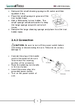
Page 25: ...es Dampen the large cleaning sponge and place it on the iron holder base 2 4 2 Connection CAUTION Be sure to turn off the power switch before connecting or disconnecting the unit Failure to do so may...

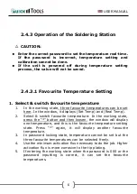
Page 26: ...ndow it displays Set Temp and Real Temp 2 Select switch favourite temperature In the working state press the button and then loosen the window will display one temperature and this is the favourite te...

Page 27: ...Setting Raise Temperature Click button the temperature will rise the LCD will display the current setting temperature If press the button for at least 1s the setting temperature will rise rapidly Loos...

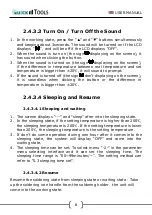
Page 28: ...20 2 4 3 4 Sleeping and Resume 2 4 3 4 1 Sleeping and waiting 1 The screen displays and sleep after into the sleeping state 2 In the sleeping state if the setting temperature is higher than 200 the sl...

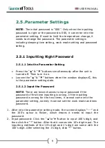
Page 29: ...e window displays C this is the parameter setting state 2 5 1 2 Input the Password NOTE There are twice chances to input password if the password of first time inputting is wrong If the inputting pass...

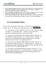
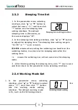
Page 30: ...1 this menu has Exit function Click or button to select the menu 1 and then click button It exits from the parameter setting and comes into the work mode 2 this menu has Sleeping Time Setting functio...

Page 31: ...eans when putting the soldering iron handle on the soldering holder it comes into the sleeping state after the setting time means the soldering iron will not come into the sleeping state 3 After finis...

Page 32: ...ace click or button to select the menu 4 and then click button into the password setting interface 2 Once into the new password setting the LCD displays After that click the or button the 100 s digit...

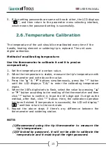
Page 33: ...er and write down the value 3 Press the buttons simultaneously press the button until the LCD displays CAL to enter the calibrating temperature mode 4 When the 100 s digit starts to flash select the v...

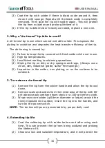
Page 34: ...ely A short tip can control the process more precise and a long or angled tip will be more suitable for components intensive PCBs 2 7 2 Use of the Tip 1 Tip temperature High temperature will shorten l...

Page 35: ...not in use When the work is finished don t leave the soldering station at high temperature for long time Or the flux in the tip will turn to oxides and carbides which will reduce the heat conductivit...

Page 36: ...rations 4 Wiping the tip on dirty or dry sponges and rags Always use a clean wet industrial grade sulfur free sponge 5 Impurities in the solder iron plating or on the surfaces to be soldered 3 To rest...

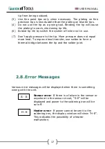
Page 37: ...the tip More pressure does not equal more heat To improve heat transfer use solder to form a thermal bridge between the tip and the solder joint 2 8 Error Messages Various error messages will be displ...

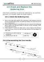
Page 38: ...ng plug when the heating element cooling down to the room temperature 2 If the values of a and b are different from the values in the following table replace the heating element or sensor or cord asse...

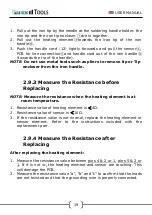
Page 39: ...nce before Replacing NOTE Measure the resistance when the heating element is at room temperature 1 Resistance value of heating element is 4 2 Resistance value of sensor is 10 3 If the resistance value...

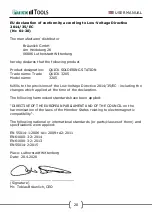
Page 40: ...4 35 EC including the changes which applied at the time of the declaration The following harmonised standards have been applied DIRECTIVE OF THE EUROPEAN PARLIAMENT AND OF THE COUNCIL on the harmonisa...

Page 41: ...USER MANUAL BEDIENUNGSANLEITUNG Br unlich GmbH Am Heideberg 26 D 06886 Lutherstadt Wittenberg Tel 49 0 3491 6181 0 Fax 49 0 3491 6181 18 e mail info quick tools de www quick tools de...

Reviews: