background image

Page 46

Exploded Views and Parts Lists

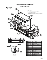
Platform Assembly

32

35

5

DWG NOTES

1) APPLY BOUNDARY DECAL (ITEM 28) 48 1/8" FROM FRONT

    EDGE OF PLATFORM TO LEADING EDGE OF DECAL.

2) APPLY BOUNDARY DECALS (ITEM 27) 1/2" ABOVE PLATFORM SURFACE

    EXCLUDING GRATING AND 1/2" FROM OUTER EDGE OF SIDE PLATE.

3) USE LOCTITE

®

 THREADLOCKER GREEN 290™ ON ROLL STOP PIVOT  

    PINS B.C.# 24932BK 2X.

4) USE LOCTITE

®

 THREADLOCKER RED 271™ ON SCREWS B.C.# 24537 4X.

5) THE ROLL STOP CYLINDER IS TO BE ADJUSTED USING A 16 GAUGE  

    (.060) SHIM PLACED BETWEEN THE ROLL STOP AND THE SIDEPLATE  

    WHERE NOTED.  ADJUST CYLINDER SO THAT THE SHIM CAN MOVE AND  

    NOT PINCHED TIGHT.

6) JAM NUT IS INCLUDED IN CYLINDER ASSY.


SCALE 1.5X

NOTE:

16 GAUGE

SHIM

24028

915R4312A-37Y

33094A

915-0414

20946

29371

13906

24932BK
28324BK

81003-000

900-0311BM

947-23750NWBM

3
2

2
1

1

9

2

8
7
6
5
4

2
2
2

15

13
12
11
10

1

2

1

5

1

1

STOP-PLATFORM
WMT-PLATFORM-NL917-2 /37" X 50"/IB

BRG-PLASTIC-FLANGE-3/8IDX1/4"
PIN-CLEVIS 3/8 X 3" EFF LEN.-W/O HOLE/BK
NUT-5/16-18 TOP LOCK/AUTO-BK
SCREW-5/16-18 X 1-1/4" SHCS BK ZINC

PIN-PLATFORM CYLINDER

WASHER-THRUST-.875" OD/.50" ID/.0585"T

RIV-POP-SD45BS-1/8"-.25/.31"

ROLL-STOP ALUM./RUBBER END/ASSY.-37"/YEL

CYLINDER-ASSY-ROLLSTOP-MILLENNIUM

947-0345NA

24550

990-0341

15328

17
16

3

1

1

3

ADAPT-CYL/ROLL STOP LEVER-OUT

915-0341N

18

1

ADAPT-CYL/ROLL STOP LEVER

LEVER-ROLL STOP LATCH-ASSY

PIVOT-ROLL STOP LEVER-L915

WASHER-.516"ID X 1"OD X .0269"/AUTO-BK

22
21
20
19

23

17192P

4

SCREW-#10-32X1/2" FHDHXS-AUTO BLK-W/PATCH

RING-1/2" EXT SNAP/AUTO-BK

10774

1

SPRING-1/4" X 1" EXT. W/HOOKS/AUTO-BK

11513

1

RIV-POP-SD64BS-3/16"-.13/.25"/AUTO-BK

36384

2

SPRING-DISC-STAINLESS-OD. 795"/ID.531"

947-3343NA

1

ASSY-LATCH-ROLL STOP

24

1

915-0147NW37YL

BRIDGE PLATE-PLT-37/48" FTG (945-0147NA37YLKS INC. 24, 36-47)

PART NO.

QTY.

ITEM

DESCRIPTION

PART NO.

QTY.

ITEM

DESCRIPTION

25

10950

1

BUMPER-RUBBER RECES.31/32" OD

25171

38
37

4

BOLT-3/8-16 X 3/4" FLBHSCS-GD8

916-5406

36

3

BEARING-UHMW FLAT-THIN-BLK

945-0431FNWBM

1

WMT-BKT-BRIDGE PLATE/FR

33603

41
40

2

BUMPER-1" X 5/8"LG NAT UHMW/BRIDGEPLATE

945-0431RNWBM

39

1

WMT-BKT-BRIDGE PLATE/RR

10001

2

BOLT-1/4-20 X 1" HEX

44
43

38660

42

1

SWITCH BUMPER

14614Z

2

NUT-1/4-20 NYLOCK / AUTO - ZINC

24012

45

2

BEARING-FLANGE-3/4" X 1/4"-12FDU04

10059BK

46

2

NUT-3/8 X 16 HEX/AUTO-BK

945-0320N

50

2

SPACER-UHMW VERTICAL CHANNEL

975-2325

48

2

PIN-PLATFORM PIVOT w/SNAP RING

31019

49

2

WASHER-1.017" ID X 1.25" OD X .07"

24443

47

2

RING-1" EXT. SNAP 


10069BK

2

WASHER-3/8" LOCK/AUTO-BK

30236R007

14

1

DECAL-BOUNDARY YELLOW VINYL 1" X 7"

18663

30236R048.5

30236R032.5

28
27
26

31
30

29

2

1

1

SCREW-1/2-20 X 1.5" SET-LOCK/AUTO-BK

DECAL-BOUNDARY YELLOW LEXAN 1" X 48 1/2"

DECAL-BOUNDARY YELLOW LEXAN 1" X 32 1/2"

BEARING-FLANGE-1" X 1/2" - 16FDU08

SPACER-FLAP CYL/0.155"

SPACER-FLAP CYL/0.540"

GUARD-WIRING-PLT-OUTER BARRIER SENSOR

4

1

2
1
1

32

33

34

35

947-0416

28031

947-0415

TUBING-POLYURETHANE 1/4"ID X 1/2"OD X .81"

1

28630R000.81

SCREW-#4-40 X 3/8" - THREAD FORM

915-0368N50YL

37049

1

33434A

HARN-ROLLSTOP OCC, NL-2

27

1

19

17

6

19

19

17

33

25

23

15

12

11

13

18

22

17

5

16

19

21

31

30

8

29

10

9

26

4

3

34

34

34

28

4

26

36

36

36

3

7

6

5

2

2

10

34

24

13

13

20

48 1/8"

NOTE:

4

NOTE:

4

NOTE:

4

NOTE:

4

NOTE:

3

NOTE:

2

NOTE:

1

NOTE:

3

SCALE 1.5X

14

47

50

50

37

48

49

41

42

40

46

43

39

44

45

37

40

38

41

45

44

43

46

48

49

NL917IB3751-2

NL917FIB3751-2

Applicable Lifts:

Summary of Contents for Millenium NL917FIB-2

Page 1: ...No 403 This lift may be installed on all vehicles appropriate for the size and weight of the lift but must be installed on buses school buses and multi purpose passenger vehicles other than motor hom...

Page 2: ...ATION CARDS MUST BE RETURNED TO THE BRAUN CORPORATION OWNER STATE ZIP Sample Warranty Registration Card Serial No Model No Two BraunAbility Serial No identification tags shown below are posted on the...

Page 3: ...hedule 10 13 Lift Electrical Schematic 15 Lift Wiring Diagram 16 Hydraulics Hydraulic Schematic 17 Hydraulics Parts List 18 Hydraulics Diagram 19 Repair Parts Pump Module Rear Pump Module Parts Lists...

Page 4: ...omatic Outboard Roll Stop Saddle 2 Outer Fold Arm 2 Opposite Pump Side Vertical Arm Bottom Parallel Arms 2 Platform Lights 2 Rear Front Outboard passenger s side Inboard driver s side of vehicle of ve...

Page 5: ...Raised Switch 32519A Threshold Alarm Microswitch Threshold Alarm Partial Fold Microswitch Assy 975 4121A Partial Fold Microswitch Note Mirror image for left rear pump lifts Bridging Microswitch 33689A...

Page 6: ...essure Adjustment procedures The inner roll stop will not raise if occupied Call BraunAbility Aftersales The outer barrier will not raise if occupied Refer to Outer Barrier Fold Pressure Adjustment pr...

Page 7: ...tform Fold Adjustment Allen Screw 1 See Tower 4 Fold Switch Adjustment in the Tower Microswitch Adjustment section for proper microswitch setting before adjusting the platform fold pressure 2 Position...

Page 8: ...positioning as detailed in Tower Microswitch Adjustment Stop Block Vertical Arm Adjustment Screw Stop blocks must make full contact Heel Inboard Outboard Toe Rear Front Outboard passenger s side Inboa...

Page 9: ...line All Lift Models Right Wrong Turn clockwise to raise outboard end of platform When adjusting platform angle setting floor level position or adjusting bridging microswitch ensure both stop blocks a...

Page 10: ...mirrored image Note Review adjustment procedures below and adjust as needed only Tower 1 Unfold Switch Adjustment Floor Position from Stow 1 Position platform at the fully stowed position using the ma...

Page 11: ...4 LO Outer Fold Arm Bearings 8 LO Saddle Bearing 2 DE Inner Fold Arm Cam Followers 4 LO Lift Tite Latch Rollers 2 LO Inner Roll Stop Lever Bearings 2 and Slots 2 LO Inner Fold Arm Roller Pin Bearings...

Page 12: ...maintenance procedures and will vary according to lift use and conditions Lifts exposed to severe conditions weather environment contami nation heavy usage etc may require inspection and maintenance p...

Page 13: ...level and remove drain plug from roll stop cylinder overflow chamber If fluid is found check again at 1 500 cycles otherwise check at 4 500 cycles If the amount of fluid increases between inspections...

Page 14: ...f needed Tighten or replace if needed Replace damaged parts and resecure as needed Apply Light Grease during reassembly procedures Replace if needed Tighten replace or correct as needed Apply Door Eas...

Page 15: ...place decals if worn missing or illegible Re place antiskid if worn or missing Inspect vertical arm plastic covers Inspect power cable Mounting Decals and Antiskid Maintenance and Lubrication Schedule...

Page 16: ...Page 14 NOTES This page intentionally left blank...

Page 17: ...8 BK 18 RD WH 18 RD WH 18 GOLD 22 GOLD 22 SILVER 22 SILVER 22 RD WH 18 GN 20 GN 20 GN 18 WH 18 OR 18 GN 18 RD 18 WH 18 BK 18 GN 18 WH 18 GN 18 GN 18 BK 20 BK 20 DK BU 20 BK 16 CB1 RD 18 RD 18 BK 18 RD...

Page 18: ...Power Relay OR BU Fold Unfold Switch WH BK GN RD L G Up Down Switch Switch Box As Viewed From Terminal Side of Switch NOT USED BLACK 6 COND DOWN RED 6 COND UNFOLD GREEN 6 COND FOLD ORANGE 6 COND UP BL...

Page 19: ...noid Valve Outer Barrier Fold Relief Solenoid Valve Outer Barrier Relief Valve 300 PSI Main Relief Valve 2500 PSI Outer Barrier Cylinder Orifice Pump Side Cylinder BACKUP PUMP Platform Fold Relief Sol...

Page 20: ...2 16004A 086 NL917FIB3551 2 16004A 088 NL917FIB3751 2 16004A 090 21 1 Hose Assembly 1 8 Pump Side NL917IB 2 NL917FIB 2 NL917IB3454 2 NL917FIB3454 2 NL917IB3751 2 NL917FIB3751 2 NL919IB 2 NL919FIB 2 16...

Page 21: ...osite Pump Side Cylinder Hydraulic Pump 22 20 21 17 2 22 23 23 19 18 18 14 15 16 12 16 28 29 24 16 8 5 5 Roll Stop Cylinder 26 25 24 13 1 31 11 4 3 10 27 Hydraulic Repair For repair of a hydraulic hos...

Page 22: ...082A 4 34 1 Cable Lift Chassis Ground 22166A 22166A 35 1 Wire Assembly Lift Interlock Connection 31797A 31797A 36 1 Wire Assembly Lift Stowed Connection tSee note below 31798A 31798A 37 1 Rubber Boot...

Page 23: ...0 35 32 36 15 15 5 33 32 7 31 30 9 10 32 32 6 6 14 18 25 24 27 3 8 18 18 UP DO WN 32819 FOLD UN FOLD 32820 39 32 20 2 21 21 1 26 24 22 Rear Pump Module Diagram Pump Mounting Bolts Apply Loctite Thread...

Page 24: ...Connection 31797A 36 1 Wire Assembly Lift Stowed Connection tSee note below 31798A 37 1 Rubber Boot Red tSee note below 82046 38 1 Control Hand Pendant Assembly Non Electronic Non Shielded Coiled tSee...

Page 25: ...15 15 5 33 32 7 31 30 9 10 32 32 6 6 14 18 25 24 27 3 8 18 18 UP DO WN 32819 FOLD UN FOLD 32820 39 32 20 2 21 21 1 26 24 22 Rear Pump Module Diagram Pump Mounting Bolts Apply Loctite Threadlocker Red...

Page 26: ...1 Cable Lift Chassis Ground 22166A 22166A 35 1 Wire Assembly Lift Interlock Connection 31797A 31797A 36 1 Wire Assembly Lift Stowed Connection tSee note below 31798A 31798A 37 1 Rubber Boot Red tSee...

Page 27: ...2 6 25 24 3 18 18 30 32 17 14 38 UP DO WN 32819 FOLD UN FOLD 32820 18 27 16 32 Front Pump Module Diagram Pump Mounting Bolts Apply Loctite Threadlocker Red 271 or equivalent to the three pump mount in...

Page 28: ...Assembly Lift Interlock Connection 31797A 31797A 36 1 Wire Assembly Lift Stowed Connection tSee note below 31798A 31798A 37 1 Rubber Boot Red tSee note below 82046 82046 38 1 Control Hand Pendant Ass...

Page 29: ...25 24 3 18 18 30 32 17 14 38 UP DO WN 32819 FOLD UN FOLD 32820 18 27 16 32 Front Pump Module Diagram Pump Mounting Bolts Apply Loctite Threadlocker Red 271 or equivalent to the three pump mount ing bo...

Page 30: ...P ZINC PLATED WASHER 10 FLAT AUTO BK BOLT 3 8 16 X 1 2 W NYLOCK PATCH BOLT SHOULDER 5 16 X 5 8 1 4 20 SS W PC 19 18 2 2 CLAMP INSULATED 1 3 8 29765 RIV POP SD66BS 3 16 25 38 AUTO BK 14993 20 21 PIN PI...

Page 31: ...2 W NYLOCK PATCH BOLT SHOULDER 5 16 X 5 8 1 4 20 SS W PC 19 18 2 2 CLAMP INSULATED 1 3 8 29765 RIV POP SD66BS 3 16 25 38 AUTO BK 14993 27208FWBM WMT LATCH LIFT TITE FRONT RETRO 27208RWBM WMT LATCH LI...

Page 32: ...ASHER 1 2 NYLON RING 5 16 EXT SNAP ZINC PLATED WASHER 10 FLAT AUTO BK BOLT 3 8 16 X 1 2 W NYLOCK PATCH BOLT SHOULDER 5 16 X 5 8 1 4 20 SS W PC 19 18 2 2 CLAMP INSULATED 1 3 8 29765 RIV POP SD66BS 3 16...

Page 33: ...1 2 W NYLOCK PATCH BOLT SHOULDER 5 16 X 5 8 1 4 20 SS W PC 19 18 2 2 CLAMP INSULATED 1 3 8 29765 RIV POP SD66BS 3 16 25 38 AUTO BK 14993 27208FWBM WMT LATCH LIFT TITE FRONT RETRO 27208RWBM WMT LATCH...

Page 34: ...ZINC PLATED WASHER 10 FLAT AUTO BK BOLT 3 8 16 X 1 2 W NYLOCK PATCH BOLT SHOULDER 5 16 X 5 8 1 4 20 SS W PC 19 18 2 2 CLAMP INSULATED 1 3 8 29765 RIV POP SD66BS 3 16 25 38 AUTO BK 14993 27208FWBM WMT...

Page 35: ...26963 4 3 2 1 7 6 5 1 1 1 2 BASE COVER ASSEMBLY 37 8 4 24440 BOLT 5 16 18 X 3 4 BHSC AUTO BK 13 12 10 16 15 14 17 1 CABLE TIE 11 SOLID 10091 4 4 26614 2 11913 4 24570 2 11541 3 29729 2 31816 O RING 5...

Page 36: ...ZINC PLATED WASHER 10 FLAT AUTO BK BOLT 3 8 16 X 1 2 W NYLOCK PATCH BOLT SHOULDER 5 16 X 5 8 1 4 20 SS W PC 19 18 2 2 CLAMP INSULATED 1 3 8 29765 RIV POP SD66BS 3 16 25 38 AUTO BK 14993 27208FWBM WMT...

Page 37: ...PTION PART NO QTY ITEM 11 1 30996BK NUT 5 16 18 ACORN 12 1 10062 WASHER 1 4 FLAT AUTO BK 6 9 5 9 7 8 10 11 12 8 14 13 15 12 2 1 3 4 6 2 10 7 1 11 24011 4 2 1 1 945 4419FNAKS BEARING FLANGE 3 4 X 3 8 1...

Page 38: ...8 12FDU06 4 24011 1 2 ARM PARALLEL BOTTOM SWITCH Incl Items 1 4 BEARING FLANGE 3 4 X 3 8 12FDU06 ASSY IB OCCUPIED 3 2 1 32514NAKS 1 945 4458NAKS 24011 4 1 ITEM PART NO QTY DESCRIPTION NUT 10 32 W LOC...

Page 39: ...RIPTION NUT 10 32 W LOCKWASHER AUTO BK 4 18349 2 4 3 1 2 ARM PARALLEL BOTTOM Incl Items 1 2 1 DESCRIPTION QTY ITEM PART NO 945 4412NAKS 1 2 BEARING FLANGE 3 4 X 3 8 12FDU06 4 24011 1 2 ARM PARALLEL BO...

Page 40: ...625 29 146 RETRACTED INCLUDES ITEMS 2 3 ELBOW 1 8 NPT 90 1 4 BARB ELBOW 7 16 20 M O RNG 37 035 ORFICE 402751 402043 403649 3 2 1 1 1 1 DESCRIPTION PART NO ITEM QTY 30 10 1 3 2 Exploded Views and Parts...

Page 41: ...1 2 FLAT AUTO BK 25346 13 3 SCREW 5 16 18 X 3 4 FHS AUTO BK 25527 14 1 BRACKET HARNESS HOSE RETAINER 401119BM 15 2 RIVET POP 1 8 13 19 SD43BS AUTO BLACK 12954 10 9 8 7 10 4 30063 RIVET PUSH IN 8MM 2...

Page 42: ...DE FRONT SMOOTH SIDE COVER PLASTIC PARALLEL ARM INSIDE REAR 945 0703NA 4 1 3 COVER PLASTIC PARALLEL ARM OUTSIDE REAR 915 0702NA 3 1 SMOOTH SIDE 2 DESCRIPTION PART NO QTY ITEM 1 2 915 0704NA DESCRIPTIO...

Page 43: ...025 15328 1 22 LEVER INBOARD BARRIER 945 0404NBM 1 23 1 16 21 22 20 18 19 DETAIL A 2 17 DETAIL A 20 19 21 23 22 13 3 4 6 7 8 12 9 11 10 5 6 8 10 7 11 1 3 4 9 5 13 14 15 16 4 QTY ITEM PART NO DESCRIPT...

Page 44: ...G DISC STAINLESS OD 795 ID 531 947 3343NA 1 ASSY LATCH ROLL STOP 24 1 915 0147NWYL BRIDGE PLATE PLT 33 48 FTG 945 0147NAY INC 24 36 47 PART NO QTY ITEM DESCRIPTION PART NO QTY ITEM DESCRIPTION 25 1095...

Page 45: ...AUTO BK 10774 1 SPRING 1 4 X 1 EXT W HOOKS AUTO BK 11513 1 RIV POP SD64BS 3 16 13 25 AUTO BK 36384 2 SPRING DISC STAINLESS OD 795 ID 531 947 3343NA 1 ASSY LATCH ROLL STOP 24 1 915 0147NW34YL BRIDGE PL...

Page 46: ...POP SD64BS 3 16 13 25 AUTO BK 36384 2 SPRING DISC STAINLESS OD 795 ID 531 947 3343NA 1 ASSY LATCH ROLL STOP 24 1 915 0147NW34YL BRIDGE PLATE PLT 34 48 FTG 945 0147NA34YLINC 24 36 47 PART NO QTY ITEM D...

Page 47: ...G DISC STAINLESS OD 795 ID 531 947 3343NA 1 ASSY LATCH ROLL STOP 24 1 915 0147NW35YL BRIDGE PLATE PLT 35 48 FTG 945 0147NA35YLKS INC 24 36 47 PART NO QTY ITEM DESCRIPTION PART NO QTY ITEM DESCRIPTION...

Page 48: ...OP SD64BS 3 16 13 25 AUTO BK 36384 2 SPRING DISC STAINLESS OD 795 ID 531 947 3343NA 1 ASSY LATCH ROLL STOP 24 1 915 0147NW37YL BRIDGE PLATE PLT 37 48 FTG 945 0147NA37YLKS INC 24 36 47 PART NO QTY ITEM...

Page 49: ...und to exist during the fourth or fifth year of warranty coverage to the following lift s power train parts Cable Cylinder Flow Control Gear Box Motor Pump Hydraulic Hose and Fittings it will be repai...

Page 50: ...ted by law notify Braun directly in writing at the above address of the unsuccessful repair s of the alleged defect s so that Braun can become directly involved in providing service pursuant to the te...

Page 51: ...ny action of Braun or any agent of Braun shall be interpreted as an extension of any warranty period or the filing limitation period in this paragraph Some states do not allow a reduction in the statu...

Page 52: ...e passenger vehicles other than motor homes with a gross vehicle weight rating GVWR that exceeds 4 536 kg 10 000 lb DOT Public Use Lift www braunability com 631 West 11th Street Winamac IN 46996 USA P...

Reviews: