INSTALLATION INSTRUCTIONS
AVMS-3700v3 INSTRUCTIONS 11-27-17
Page 21 of 31
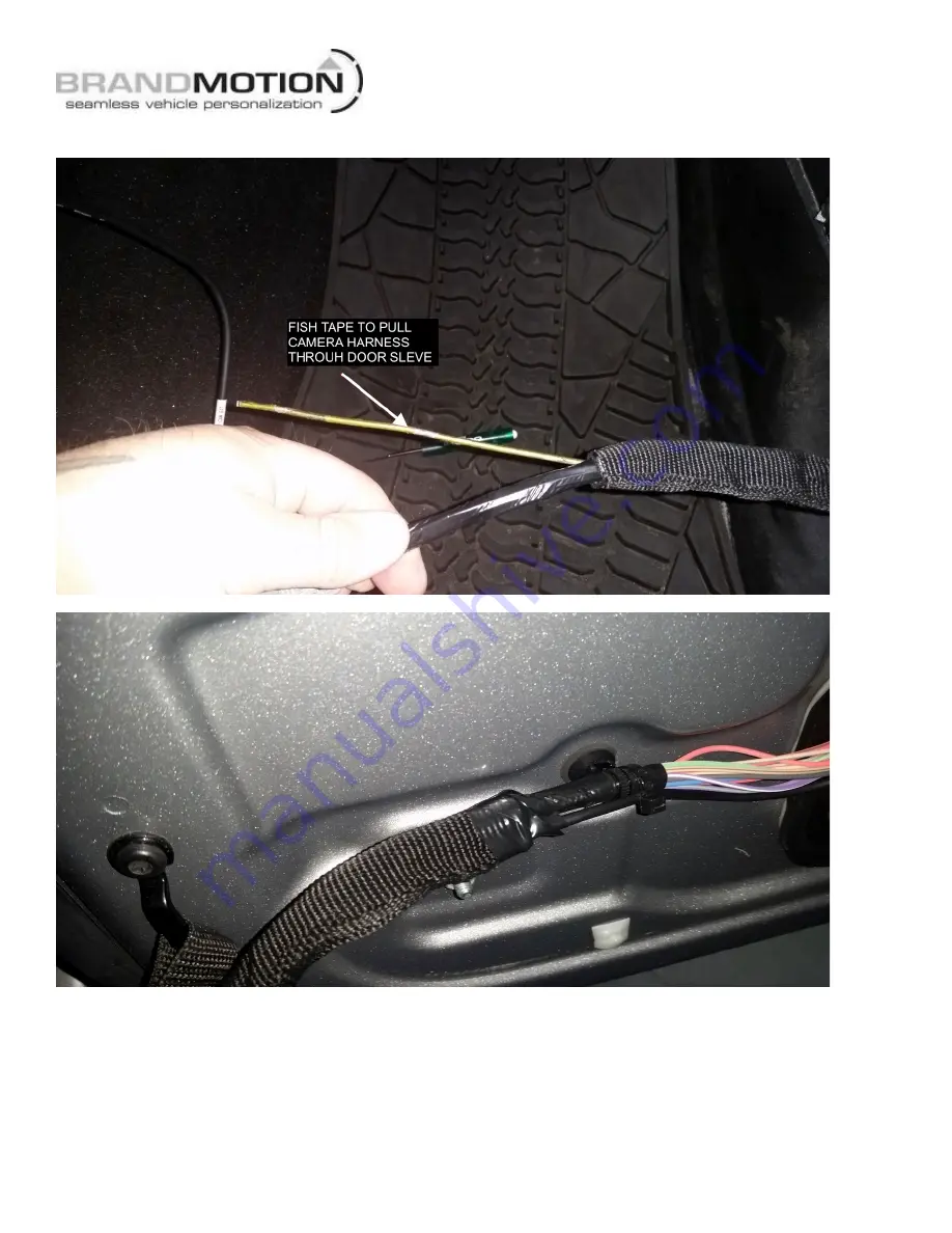
24.
Run the camera wire through the factory door sleeve. Use a long zip tie or a fish tape.
Page 1: ...video output RCA cables Power camera input harness 2 side camera templates Mounting screws and gaskets These instructions Wire strippers Wire cutters Electrical tape Zip ties Plastic panel removal to...
Page 2: ...NAL PROGRAMMING NOTE We strive to provide accurate and up to date installation instructions For the latest full color instructions as well as an installation video please visit www brandmotion com REA...
Page 3: ...INSTALLATION INSTRUCTIONS AVMS 3700v3 INSTRUCTIONS 11 27 17 Page 3 of 31 3 Mount the bracket on the rear tire mount after bracket is on slide on the 3 push nuts over the studs...
Page 4: ...INSTALLATION INSTRUCTIONS AVMS 3700v3 INSTRUCTIONS 11 27 17 Page 4 of 31 4 Run the harness into the rear gate through the factory grommet 5 Run rear camera harness through top hole of tire carrier...
Page 5: ...ent Bracket for Camera Clearance using Phillips Screwdriver and 3 8 Wrench or Socket Drive Note Short Bracket has been designed for Factory offset wheels Use the Long Bracket for wheels with larger of...
Page 6: ...TION INSTRUCTIONS AVMS 3700v3 INSTRUCTIONS 11 27 17 Page 6 of 31 7 Use a T20 Torx bit to remove subwoofer box If equipped with subwoofer box 8 Using a plastic trim removal tool pry off rear seat belt...
Page 7: ...lastic trim removal tool remove rear access panel to expose 10mm bolt and remove bolt 10 Run the rear camera harness alone the factory harness Use zip ties to secure to the factory harness 11 Run the...
Page 8: ...box area on the passenger side of the vehicle Coil any excess harness and place in passenger kick panel area 13 Remove the glove box to gain access to the back side by pressing the side of the inter g...
Page 9: ...ge 9 of 31 SIDE CAMERA INSTALL 1 Place template stickers under the side mirrors The arrow should be perpendicular to the vehicle body pointing away for the vehicle Or use the plastic guides for the co...
Page 10: ...700v3 INSTRUCTIONS 11 27 17 Page 10 of 31 3 Remove the door panel from the vehicle remove trim behind door handle and remove the torx screw 4 Remove the inter trim on the pull handle to gain access to...
Page 11: ...INSTALLATION INSTRUCTIONS AVMS 3700v3 INSTRUCTIONS 11 27 17 Page 11 of 31 5 Remove the 2 Torx in the lower front of the door...
Page 12: ...the door panel removed unplug the mirror harness and connect a pull wire to be able to pull the harness back through the door 7 Remove 2 Torx bolts on the inner door frame to remove mirror When the b...
Page 13: ...S AVMS 3700v3 INSTRUCTIONS 11 27 17 Page 13 of 31 8 Remove the mirror and pull harness through the door 9 Repeat for the other side 10 Compare the mirrors to see it the templates are in the same place...
Page 14: ...S 3700v3 INSTRUCTIONS 11 27 17 Page 14 of 31 11 Remove the 3 Torx screws from inside the mirror You can fairly easy get behind the mirror glass to do this The picture show the glass already removed to...
Page 15: ...AVMS 3700v3 INSTRUCTIONS 11 27 17 Page 15 of 31 12 Remove the mirror glass by gently lifting on the plastic tabs holding the glass to the mirror motor 13 Drill the hole in the template for the camera...
Page 16: ...S 11 27 17 Page 16 of 31 14 Mount the left camera the camera metal bracket will have a LH stamped on it in the side mirror pod marked 15 Stick the foam gasket to the flat side of the mirror pod then m...
Page 17: ...7 Page 17 of 31 16 Tape the terminals to a zip tie to help guide the wire through the back of the mirror and mounting arm Run the camera harness though the back of the mirror where the factory power h...
Page 18: ...g the factory harness run the camera harness though the mounting base and pull the rest of the camera harness through 18 Attach the camera harness and the factory mirror harness to the pull wire that...
Page 19: ...ONS 11 27 17 Page 19 of 31 19 Notch the grommet to allow room for the camera harness 20 Remount the mirror to the vehicle with the 2 Torx bolts 21 Insert the camera pins into the connector for the cam...
Page 20: ...INSTALLATION INSTRUCTIONS AVMS 3700v3 INSTRUCTIONS 11 27 17 Page 20 of 31 23 Run the camera harness along the factory harness in the door...
Page 21: ...INSTALLATION INSTRUCTIONS AVMS 3700v3 INSTRUCTIONS 11 27 17 Page 21 of 31 24 Run the camera wire through the factory door sleeve Use a long zip tie or a fish tape...
Page 22: ...cation as the factory door connector 26 Run the camera wire to behind glove box area to connect to the 360 main control module Passenger side camera harness may have excess length coil excess and zip...
Page 23: ...of 31 FRONT CAMERA INSTALL 1 Front camera will mount under the front bumper on the metal bumper 2 Mark location of the camera on the metal bumper These next steps will vary due to the different types...
Page 24: ...and out in front of the vehicle 4 You can use the plastic mount provided for the front camera Or make your own 5 The white sticker on the camera is up 6 Route the camera harness into the vehicles inte...
Page 25: ...TION 1 Place the keypad on the dash in an easy to reach location such as in front of the center console 2 Run the keypad harness to the glove box area 3 For factory display radios the power button on...
Page 26: ...d to accessory power at the power point on the dash The wire color is Blue Red 3 The blue wire will be connected to reverse in the passenger kick panel The wire color is White Gray 4 The RCA from the...
Page 27: ...screen There will be a WARNING message on the screen over the 360 image until unit is calibrated 8 Shift back into park Press the power button on the 2 button keypad once to see if the 360 image comes...
Page 28: ...27 17 Page 28 of 31 Mounting the 360 main control module 1 Mount the 360 main control module behind the glove box on the ridged plastic duct Mount the module long ways with the connector facing up Use...
Page 29: ...INSTALLATION INSTRUCTIONS AVMS 3700v3 INSTRUCTIONS 11 27 17 Page 29 of 31 2 Zip tie up wire harness to keep out of way of metal heater lines behind glove box area...
Page 30: ...INSTALLATION INSTRUCTIONS AVMS 3700v3 INSTRUCTIONS 11 27 17 Page 30 of 31 Wiring schematics and pin outs...
Page 31: ...INSTALLATION INSTRUCTIONS AVMS 3700v3 INSTRUCTIONS 11 27 17 Page 31 of 31...