DCD-24 User Manual (rev 1.00)
Page 11
Page 10
DCD-24 User Manual (rev 1.00)
13. Ethernet
The Ethernet port is used to connect the DCD-24 to a network via standard TCP/IP
protocol. It enables the user to access the DCD-24 remotely, and to upload firmware
from any computer on the network.
The first thing needed is to set its IP address properly using the front panel keys.
13.1. ETHERNET IP SETTINGS
The IP address setup mode is entered when you hold down the [
setup
] key. What
you then view on the display are portions of a long string of characters made up of
the following (default values shown):
• DHCP Y/N
• IP 192.168. 0.120
• M 255.255.255. 0
• GA 192.168. 0. 1
where “M” indicates the mask and “GA” the gateway address.
[
left
] and [
right
] keys navigate through the strings 3 digits at a time (approximately),
so all of the possible views of the above would be:
• DHCP N (or Y)
• I P 192.
↔
192. 168.
↔
168. 0.
↔
0. 120
• M 255.
↔
255. 255.
↔
255. 255.
↔
255. 0
• GA 192.
↔
192. 168.
↔
168. 0.
↔
0. 1
The [
up
] and [
down
] keys always control the right-most digit, which is normally flashing.
In DHCP mode (“DHCP Y”), the addresses are not adjustable, but serve to display the
values assigned by the DHCP address server.
13.2. MAIN HTML PAGE
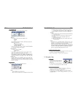
Once your IP settings are entered properly, use any browser (Firefox, Explorer …)
and enter the IP address of your DCD-24 to display the main HTML
page.
Header
The header of the HTML page includes the Serial Number, the IP Address and the
Firmware. This information comes from the unit and cannot be edited here.
Also included is the Device Name. To change it, click on the name area and a
text box will open up. Type in a new name (up to 32 characters) an hit Enter.
Or hit Esc to get out without any change.
In the upper right corner is the UPDATE FIRMWARE button. Clicking this takes
you to a separate specialized page. See chapter 14.
9. Non-Volatile Storage
The DCD-24 has non-volatile memory holding all the DCD-24 settings such as rate
and reference selection. This memory is continuously updated so that, when the
unit is turned on, it is in the same condition as it was when powered down.
NOTE: You should wait approximately 10 seconds after a change was entered
before powering down, to allow for the flash memory to be updated
10. Lock Status
The lock status of the DCD-24 is indicated in the STATUS led section:
• LOCKED
Good and locked
• HOLDING Holding last known frequency after lock failure
The DCD-24 always tries to lock to its input. Once the rate has been established, if
the reference is off speed by more than 10%, it starts slewing. Note that with video,
the 10% rule applies to the horizontal frequency and not the frame rate.
While slewing, the LOCKED led is flashing. Once lock has been established, the
DCD-24 may need to adjust the phase. During the phase locking adjustment, the
LOCKED led flashes rapidly.
11. Defining the reference rate
The DCD-24 always measures the input reference and determines it’s rate.
OFF SPEED: When the reference is detected to be off speed by more than 1.5%,
the DCD-24 alerts the user by illuminating the REF OFF SPEED led in the
WARNING section. The generated frequency will track the reference and
be off by the same percentage.
12. Source Reference Failure
In the event of failure of the external reference, the DCD-24 holds the last known fre
-
quency and displays “HOLDING” as a lock status.
If a signal is still present at the main reference input, the DCD-24 automatically attempts
to lock to it again. If it succeeds, it goes through the normal ‘Locked’ sequence; if not, it
continues holding and attempts to Lock to the main reference again.
If no signal is present at the main reference input, the DCD-24 will remain in
‘HOLDING’ mode indefinitely.


