background image


TABLE OF CONTENTS 


1.


GENERAL .............................................................................................. 4


1.1


I

NSTRUCTIONS

...............................................................................................................4


1.2


S

TANDARDS

,


C

ERTIFICATES AND 

A

PPROVALS

..................................................................6


1.3


B

ASE 

S

TANDARDS FOR 

EMC


&


S

AFETY

..........................................................................6


1.4


P

ROTECTIVE CLASS

........................................................................................................6


1.5


T

RANSPORT 

&


S

TORAGE CONDITIONS

.............................................................................7


1.6


O

PERATING CONDITIONS

.................................................................................................7


1.7


LCD

 SPECIFICATIONS

.....................................................................................................8


1.8


P

ACKAGE CHECK LIST

.....................................................................................................8


2.


PRODUCTS OVERVIEW ....................................................................... 9


2.1.1


Technical Specifications .......................................................................................9


3.


ORDERING CODE ............................................................................... 11


3.1


HMI

 ORDERING CODE

...................................................................................................11


3.2


HMI


S

PARES PART LIST

................................................................................................12


3.2.1


HMI 4.3” ..............................................................................................................12


3.2.2


HMI 7” (Low Cost) ...............................................................................................12


3.2.3


HMI 7” (High Performance).................................................................................12


3.2.4


HMI 10” ...............................................................................................................13


3.2.5


HMI 15” ...............................................................................................................13


3.3


R

ESERVED

...................................................................................................................14


3.4


A

CCESSORIES PART NUMBERS

......................................................................................14


4.


INSTALLATION .................................................................................... 15


4.1


I

NSTALLATION

...............................................................................................................15


4.2


D

IMENSIONAL DRAWINGS

..............................................................................................17


4.2.1


Dimensional drawings of the HMI 4.3” ................................................................17


4.2.2


Dimensional drawings of the HMI 7” ...................................................................18


4.2.3


Dimensional drawings of the HMI 10” .................................................................19


4.2.4


Dimensional drawings of the HMI 15” .................................................................20


4.3


M

OUNTING

...................................................................................................................21


4.4


P

OWER 

S

UPPLY

...........................................................................................................22


4.5


I

NTERFACES

.................................................................................................................24


4.5.1


COM1 port, DB9 male (RS232C)........................................................................24


4.5.2


COM2 port, DB25 Female (RS232C/RS422/RS485) .........................................25


4.5.3


COM3 (Reserved) ...............................................................................................26


4.5.4


Ethernet...............................................................................................................26


4.5.5


USB Host ............................................................................................................26


4.5.6


SD slot.................................................................................................................26


4.5.7


Sound input/Output .............................................................................................27


4.5.8


Reserved.............................................................................................................27


4.6


R

EAL 

T

IME 

C

LOCK

........................................................................................................27


4.7


HMI


R

ESET 

P

ROCEDURE

..............................................................................................27


Summary of Contents for HMI 10

Page 1: ...UMHW01A Rev 3 2012 User Manual HMI Hardware ...

Page 2: ...to malfunctioning of equipment damage or repair Protective Earth DC Supply PREFACE Original equipment manufacturer reserves the right to change information available in this document without notice Original Equipment manufacturer is not liable for any damages incurred to equipment personal during installation or use of equipment as explained in this document User must acquire sufficient knowledge ...

Page 3: ...h Performance 12 3 2 4 HMI 10 13 3 2 5 HMI 15 13 3 3 RESERVED 14 3 4 ACCESSORIES PART NUMBERS 14 4 INSTALLATION 15 4 1 INSTALLATION 15 4 2 DIMENSIONAL DRAWINGS 17 4 2 1 Dimensional drawings of the HMI 4 3 17 4 2 2 Dimensional drawings of the HMI 7 18 4 2 3 Dimensional drawings of the HMI 10 19 4 2 4 Dimensional drawings of the HMI 15 20 4 3 MOUNTING 21 4 4 POWER SUPPLY 22 4 5 INTERFACES 24 4 5 1 C...

Page 4: ...control systems military systems and any other application where performance failure could be life threatening or otherwise catastrophic Disassembling or Modification Do not disassemble or modify LCD module It may damage sensitive parts inside LCD module and may cause scratches of dust on display Manufacturer does not warrant the module if customers disassemble or modify LCD module Breakage of LCD...

Page 5: ...y with absorbent cotton or other soft material Wipe off saliva or water drops as soon as possible If saliva or water drops contact with polarizer for a long time they may cause deformation or color fading When cleaning the adhesives please use absorbent cotton wetted with a little petroleum benzene or other adequate solvent Static Electricity Protection film must remove very slowly from the surfac...

Page 6: ...y electromagnetic fields IEC 61000 4 3 2006 A1 2007 A2 2010 Electrical fast transient burst IEC 61000 4 4 2004 A1 2010 Surge IEC 61000 4 5 2005 Conducted disturbances induced by radio frequency fields IEC 61000 4 6 2008 Power frequency magnetic field IEC 61000 4 8 2009 Voltage dips short interruptions and voltage variations IEC 61000 4 11 2004 Emission from Electromagnetic fields CISPR 11 2009 A1 ...

Page 7: ...y modules 1 Room ambient temperature 15 0 to 35 0 C and 65 RH or less 2 Do not store in surroundings containing organic solvent or corrosive gas 3 Store HMI in anti electrostatic container or bag 1 6 Operating conditions Description Details Temperature 0 0 C to 50 0 C Relative Humidity 10 to 90 no condensation Altitude 2000 meters maximum Pollution Degree 2 Sinusoidal vibration conforming to IEC 6...

Page 8: ...015G G Hz from 5 200 Hz 6bB Octave from 200 500 Hz 2 hrs for each direction of X Y Z Package drop test 10 drops from 60 cm on 1 corner 3 edges 6 surfaces Typical View Angle Model HMI 4 3 HMI 7 LOW COST HMI 7 HIGH PERFORMANCE HMI 10 HMI 15 Vertical Up Down 50 O 70 O 50 O 70 O 50 O 70 O 60 O 70 O 80O 80 O Horizontal Left Right 70 O 70 O 70 O 70 O 70 O 70 O 75 O 75 O 85 O 85 O 1 8 Package check list ...

Page 9: ...X 152 304 X 228 MTBF back light at 25 0 C 30 000 hrs 50 000 hrs 50 000 hrs 50 000 hrs 50 000 hrs Backlight LED LED LED LED CCFL Brightness Adjustment Yes Yes Yes Yes Yes Screen Saver Yes Yes Yes Yes Yes Language Fonts Yes Yes Yes Yes Yes Main Hardware Processor CPU speed ARM11 533Mhz ARM11 533Mhz ARM Cortex A8 667Mhz ARM Cortex A8 667Mhz ARM Cortex A8 667Mhz Flash Memory ROM 128 MB 128 MB 128 MB 1...

Page 10: ...es Outer dimensions W X H X D mm 140 X 116 X 57 212 X 156 X 57 212 X 156 X 57 325 X 263 X 56 400 X 310 X 56 Mounting depth mm 51 51 51 50 50 Panel cut W X H mm 123 1 X 99 1 197 1 X 141 1 197 1 X 141 1 310 1 X 248 1 367 1 X 289 1 Protection IP65 front IP20 rear IP65 front IP20 rear IP65 front IP20 rear IP65 front IP20 rear IP65 front IP20 rear Front bezel housing Plastic plastic Plastic plastic Alu...

Page 11: ...supply Enclosure 1 11 to 36V DC 0 Standard 2 90 to 250 V AC 1 Stainless Steel Sound Input Output 3 DI 3DO 0 None 1 Yes SD card slot 0 None 1 Yes Ethernet 0 None 1 Yes Other Networks 0 None Software 0 None Specify WinCE Core or WinCE Professional version as special note at Software 1 0 1 0 0 0 1 1 1 1 1 1 0 0 ...

Page 12: ...lay Module 322MODU LM0731 A0 Power Fuse 4 Amp DC power 10350 15402 01 00 DC power plug 10343 1103A 00 00 AC power plug 10343 1103A 01 00 Resistor 2 4 1w AC power 10301 42409 55 00 3 2 3 HMI 7 High Performance Part Number Part number Main Board HMA075 IO Board HIO075 Sound Board HSB075 90 250VAC power board HPM751 11 36VDC power board HPM752 LCD Display Module 323MODU LM0751 A0 Power Fuse 4 Amp DC ...

Page 13: ...3 2 5 HMI 15 Part Number Part number Main Board HMA155 Backlight Board HBL155 Sound Board HSB105 90 250VAC power board HPM751 11 36VDC power board HPM754 LCD Display Module 325MODU LM1551 A0 Power Fuse 6 3 Amp AC power 10350 15632 01 00 Resistor 2 4 1w AC power 10301 42409 55 00 DC power plug 10343 1103A 00 00 AC power plug 10343 1103A 01 00 DI DO plug 10343 1208B 00 00 It is possible to change po...

Page 14: ...et for HMI 4 3 For dust and Moisture protection WPG073 Gasket for HMI 7 LOW COST HMI 7 HIGH PERFORMANCE For dust and Moisture protection WPG105 Gasket for HMI 10 For dust and Moisture protection WPG155 Gasket for HMI 15 For dust and Moisture protection HMB045 HMI Mounting Brackets ...

Page 15: ... When HMI is installed inside main panel make sure that proper vents are available for the main panel ambient temperature inside the panel is not exceeded beyond HMI specifications operator is alerted incase of exceeding temperature limits 9 When HMI is installed on panel front door check depth of the HMI and make sure that there is enough clearance available inside the panel after closing the mai...

Page 16: ...voltage levels with a multimeter before connecting them with HMI 17 While using HMI with stainless steel front for wash down applications make sure that panels enclosures cabinets housings are perfectly closed to avoid water entry inside panels causing damages to the equipment and injury to operating personal 18 Improper installation voids warranty ...

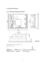
Page 17: ...nsional drawings 4 2 1 Dimensional drawings of the HMI 4 3 Note All dimensions are in mm Tolerance 1 mm Panel cutout 123 1 X 99 1 DB9 Male Network option LAN Ethernet RJ45 SD slot DB25 Female USB port Power supply ...

Page 18: ...sional drawings of the HMI 7 Note All dimensions are in mm Tolerance 1 mm Panel cutout 197 1 X 141 1 DB9 Male LAN Ethernet RJ45 SD slot DB25 Female USB port Power supply Network option Terminals for DI DO future use ...

Page 19: ...Dimensional drawings of the HMI 10 Note All dimensions are in mm Tolerance 1 mm Panel cutout 310 1 X 248 1 DB9 Male Network option LAN1 Ethernet RJ45 SD slot DB25 Female LAN2 Ethernet RJ45 Power supply USB port ...

Page 20: ...Dimensional drawings of the HMI 15 Note All dimensions are in mm Tolerance 1 mm Panel cutout 367 1 X 289 1 DB9 Male LAN1 Ethernet RJ45 SD slot DB25 Female LAN2 Ethernet RJ45 Power supply Network option USB port ...

Page 21: ...MI startup about how to select angle for vertical installation Horizontal Installation Model HMI 4 3 HMI 7 LOW COST HMI 7 HIGH PERFORMANCE HMI 10 HMI 15 Width mm 123 1 197 1 197 1 310 1 367 1 Height mm 99 1 141 1 141 1 248 1 289 1 Depth mm 51 51 51 50 50 Vertical Installation Model HMI 4 3 HMI 7 LOW COST HMI 7 HIGH PERFORMANCE HMI 10 HMI 15 Height mm 99 1 141 1 141 1 248 1 289 1 Width mm 123 1 197...

Page 22: ...s for HMI with Plastic enclosures Top view Bottom View Tighten all mounting clips otherwise it may effect the touch panel operation and ingress protection will be compromised 4 4 Power Supply The following options are available 1 AC Power 90 250 V AC 47 63 Hz Universal AC power supply Except HMI 4 3 2 DC Power 11 36 V DC ...

Page 23: ...n potentially explosive environments If any service is required switch off the power supply and bring HMI to environment which is clean Use proper tools to open HMI enclosure Repairs servicing should be done by personal qualified trained experienced and authorized to perform these kind of tasks Dangerous high voltages may be present in parts of PCB and improper servicing may cause shock and fatal ...

Page 24: ...minal block for connecting the power supply is supplied along with HMI and is designed for cables with a maximum cross section of 1 5 mm 2 4 5 Interfaces Tighten all the screws after inserting connector at COM1 COM2 otherwise communication failure with connected PLC Inverter devices may occur because of loose connections 4 5 1 COM1 port DB9 male RS232C Fig DB9 male Pin number Signal Signal Name Si...

Page 25: ...RS232C 6 DSR Data set ready Input RS232C 7 SG Signal Ground 5V RS232C 8 DCD Data carrier detect Output RS232C 9 10 11 12 TXDA Transmit data Output RS422 RS485 13 TXDB Transmit data Output RS422 RS485 14 RTSA Request to send Output RS422 15 RTSB Request to send Output RS422 16 17 18 CTSA Clear to send Input RS422 19 CTSB Clear to send Input RS422 20 DTR Data terminal ready Output RS232C 21 5 V 5 V ...

Page 26: ...d HMI 15 two Ethernet ports are supported 4 5 5 USB Host Fig USB connector 4 5 6 SD slot Use only SD card recommended by manufacturer Pin Description 1 Transmit TX 2 Transmit TX 3 Receive RX 4 No connection 5 No connection 6 Receive RX 7 No connection 8 No connection Pin Description 1 5V DC max 100 mA 2 USB DN 3 USB DP 4 GND ...

Page 27: ...input output connector Use 3 5mm diameter with 14mm length stereo phone plug 4 5 8 Reserved 4 6 Real Time Clock Item Description Make Seiko Instruments Model MS621 FL11E Rating 3V 4 mAH Typical life time 10 yrs Buffer period 6 months Type Rechargeable Accuracy Maximum 2 sec day 4 7 HMI Reset Procedure Short Pin no 2 and Pin no 3 at COM2 in HMI Then Power ON the HMI ...

Page 28: ...rt link across Pin2 and Pin3 at COM2 and then press OK Now complete the calibration of touch screen at HMI This reset procedure will clear all the contents in Resident flash and load default factory settings into Flash memory ...

Reviews: