background image

LD-5010 

Installation

18


8/24/2017

 Bradley 

• 215-1869 Rev. B; ECN 17-11-004B

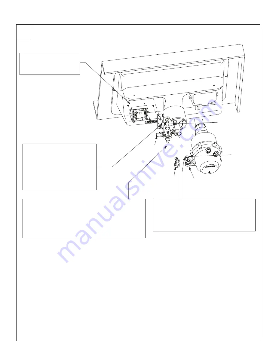
Control Box and Valve Installation

10

Secure control box to 
underside of bowl using 
(2) #10 x 1/2" long screws 
provided.

A

1/4"  Water  Supply  

Outlet with 

Compression Nut

Cold Supply

Hot Supply

Cold

Hot

Attach 1/4" supply tube from the 
WashBar to the 1/4" supply valve 
outlet. Loosen the compression 
nut on the valve body. Push the 
1/4" supply tube firmly into the 
tube connector until it is fully 
seated. Tighten the compression 
nut by hand.

B

For thermostatic mixing valve installation, secure 1/2" supply 
hose to hot water supply valve inlet. Secure the other supply 
hose from cold water supply to cold water supply valve inlet. 
Secure valve to bowl using (2) #10 x 1/2" long screws.
For tempered line installation, secure 1/2" supply hose 
to tempered water supply and TL valve inlet (not shown). 
Secure valve to bowl using (2) #10 x 1/2" long screws.

C

3/8" 

Compression 

Nut

Remove 3/8" compression nut/sleeve from the 
hot and cold supply stop valves. Connect 3/8" 
end of flexible supply hose to 3/8" compression 
on supply stop valve. Ensure hot and cold supply 
hoses are connected to hot and cold supply stop 
valve. For TL option, only connect cold supply.

D

Summary of Contents for LD-5010

Page 1: ...Dimensions 5 10 Structural Rough Ins 11 Plumbing and Electrical Rough Ins 12 Drain Assembly 13 WashBar Installation 13 Aerator Installation 14 Attach Soap Motor and Soap Container Bracket 14 Bowl Moun...

Page 2: ...ound under Products on our Web site at www bradleycorp com Separate parts from packaging and make sure all parts are accounted for before discarding any packaging material If any parts are missing do...

Page 3: ...ew 160 353 O Ring 125 111 Drain Adapter Packing Washer 10 24 Screw Drain Adapter Prepack S45 2480 Master Control Box S39 845 10 x 3 8 Screw 2x P18 054 Access Panel Bracket 140 1172 10 Access Panel Thu...

Page 4: ...269 2519 Casting ASM WashBar Chrome w LED S05 214F01 Union Tube 1 4 OD 269 624 1 4 x 60 Tubing 269 547C For Service 1 Increments R68 600011 Elbow 1 4 x 3 4mm Hose Barb 145 221 Gasket WashBar Deck Soa...

Page 5: ...5010 Bradley 215 1869 Rev B ECN 17 11 004B 8 24 2017 5 Dimensions 1 Person Top View Front View mm 30 762 20 1 2 521 5 127 11 1 2 292 13 1 2 343 3 1 8 79 11 279 10 3 4 273 5 127 19 1 8 485 22 1 2 571 5...

Page 6: ...tion 6 8 24 2017 Bradley 215 1869 Rev B ECN 17 11 004B Dimensions 2 Person Top View Front View mm 60 1524 20 1 2 521 11 1 2 292 10 3 4 273 5 127 13 1 2 343 3 1 8 79 11 279 19 1 5 485 5 127 5 127 22 1...

Page 7: ...ation LD 5010 Bradley 215 1869 Rev B ECN 17 11 004B 8 24 2017 7 Dimensions 3 Person Top View Front View mm 20 1 2 521 11 1 2 292 10 3 4 273 5 127 13 1 2 343 3 1 8 79 19 1 5 485 5 127 5 127 22 1 2 571...

Page 8: ...allation 8 8 24 2017 Bradley 215 1869 Rev B ECN 17 11 004B Dimensions 4 Person Top View Front View mm 20 1 2 521 11 1 2 292 10 3 4 273 5 127 13 1 2 343 3 1 8 79 19 1 5 485 5 127 5 127 22 1 2 571 11 27...

Page 9: ...depth must be 20 1 2 minimum for ADA Enhanced Reach depth is only 20 1 2 Deck depth must be 20 1 2 minimum for ADA Enhanced Reach depth is only 20 1 2 20 1 2 521 8 203 34 864 33 1 2 851 27 686 9 229...

Page 10: ...nsions Side View mm 20 3 4 527 8 1 16 205 33 1 16 787 28 15 16 735 13 3 4 350 16 15 16 432 13 7 8 352 19 3 16 488 27 685 11 13 16 300 11 1 8 282 22 1 2 565 9 13 16 250 34 1 16 865 28 15 16 735 27 685...

Page 11: ...chors for Soap Tank Bracket 100 lb pull out force 4 13 1 4 min 337 13 1 4 min 337 9 229 33 1 2 851 Deck Height 21 3 4 552 15 5 8 396 3 4 19 15 9 16 394 10 3 8 264 3 1 4 83 5 1 2 140 13 330 10 3 8 264...

Page 12: ...T Drain Stub out 2 from wall 1 H C Nominal O D Comp Hot Cold supplies Stub out 2 from wall 1 E 110V GFI protected electrical outlet 15 amp circuit breaker 1 C L 9 229 33 1 2 851 Deck Height 23 3 4 603...

Page 13: ...cure from underside with nuts and grounding washer right side only D WashBar Grounding Washer 25 QC Nut WashBar 1 3 8 18 Connect grounding wire supplied by installer to grounding washer and ground per...

Page 14: ...interior white cylinder that fits into the soap container This fit up may be tight Move the soap pump laterally while applying pressure to seat into soap container opening Soap Motor Control Box Soap...

Page 15: ...Push drain cap down until drain cap is flush with basin Grommets should hold drain cap securely against drain trough walls A To remove drain cap carefully slip flat screwdriver into left or right hand...

Page 16: ...and RJ45 connector cable from motor and discard G Bundle loose cords to motor using hook and loop cable tie F Flexible Hose Hose Clamp Front View of Motor CAUTION If dryer motor is not secured proper...

Page 17: ...Installation LD 5010 Bradley 215 1869 Rev B ECN 17 11 004B 8 24 2017 17 Attach Power Line Filter 9 Secure dryer power line filter to underside of bowl using 2 10 x 1 screws provided A...

Page 18: ...and B For thermostatic mixing valve installation secure 1 2 supply hose to hot water supply valve inlet Secure the other supply hose from cold water supply to cold water supply valve inlet Secure valv...

Page 19: ...Ensure that the soap tube is not kinked Position hand above soap motor control box and adjust tube if needed F Slide gallon jug with soap pump into soap motor control box Ensure soap pump flange is po...

Page 20: ...he same connections After all connections are made reference Master Control Box System Startup section later in this manual D Adjust Temperature with Water Running H C A Loosen Cap Screw about 1 4 4 6...

Page 21: ...anel up and check fitup between thumbscrews and panel slots Rotate access panel down and make adjustment to brackets if necessary Install bottom 10 fastener into brackets C Rotate access panel up and...

Page 22: ...hBar is powered up there is a sequence of LEDs that will light up Within 5 10 seconds of receiving power the WashBar will cycle it s LED lights RED GREEN and then BLUE Once the LEDs turn blue the Wash...

Page 23: ...mode While in operating mode The soap and water can activate at the same time but the dryer cannot activate at the same time as the soap and water When dryer is active disable water sensor closest to...

Page 24: ...soap LED flashes indicating the 2 in 248 000 Next there will be a 1 5 second solid red water LED followed by 4 white soap LED flashes indicating the 4 in 248 000 Finally a 1 5 second solid red dryer L...

Page 25: ...will cycle until hand is removed 2 Continue to hold hand under water until desired setting color is shown then remove hand while color is being displayed Blue LED Bright standby LEDs ON default when W...

Page 26: ...software version and cycle counts for the soap water and dryer To view the LCD display 5 Open the access panel 6 Locate the LCD screen on the master control board The display will cycle through the s...

Page 27: ...your way toward the more complicated Routine cleaning Daily or as often as needed use a solution of warm water and soap detergent or ammonia Apply the cleaning solution per the manufacturer s instruct...

Page 28: ...grade rubber and plastic components They will also cause skin irritation Most inexpensive soaps typically the pink lotion type fall into this acidic category and will eventually cause valve failure an...

Reviews: