BRADEN PCD24B Installation Maintenance And Service Manual Download Page 18

STATIC BRAKE SERVICE

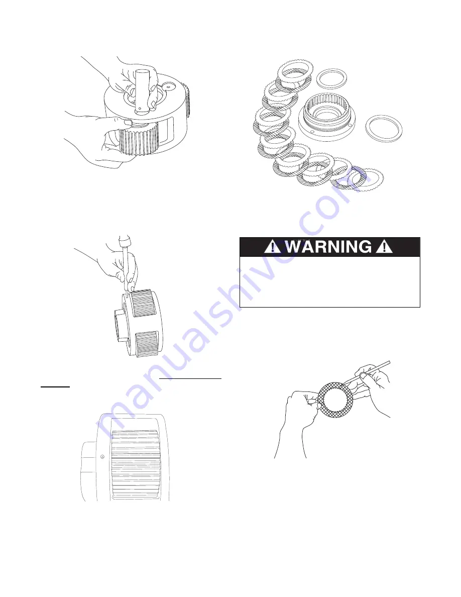
1. Remove all friction and steel discs (items 27 & 28)
and both spacer plates (item 24) from the motor adapter. 

1. Thoroughly clean and inspect all parts at this time.
Check brake piston sealing surfaces on motor adapter
and brake cylinder (item 2) for damage or excessive
wear. Be sure the brake release port in the brake cylin-
der is open and free of contamination.

2. Place each friction disc on a flat surface and check
for distortion with a straight edge. Friction material should
appear even across entire surface with groove pattern
visible. Replace friction disc if splines are worn to a point,
disc is distorted, friction material is worn unevenly, groove
pattern is worn away or friction material is burned. Place
each steel disc on a flat surface and check for distor-
tion with a straight edge. Check surface for signs of mate-
rial transfer or heat. Replace steel disc if splines are
worn to a point, disc is distorted or heat discolored.

16

Assembly

1. Insert two bearings with a spacer between them into
a planet gear. Place a thrust race on each side of the
gear and position this assembly in the planet carrier.
Slide the planet gear shaft through the carrier and gear
assembly, aligning the pin hole in the shaft with the hole
in the carrier.

2. Drive a NEW rollpin into place. 

Always use NEW

rollpins.

When properly positioned, 50% of the rollpin

length should be engaged in the planet gear shaft with
the remaining 50% in the carrier.

3. With a center punch, stake the carrier next to the pin
hole. This will distort the hole in the carrier so the rollpin
will not back out when in service. Repeat steps 1 through
3 for each of the other two gears.

DO NOT CLEAN BRAKE FRICTION DISCS 
IN SOLVENT. SOLVENT MAY CAUSE 
DAMAGE TO FRICTION MATERIAL WHICH
MAY RESULT IN BRAKE FAILURE AND 
LOSS OF LOAD CONTROL.

Summary of Contents for PCD24B

Page 1: ...STALLATION MAINTENANCE AND SERVICE MANUAL LIT2152 REV 2 9 2007 PACRWINCH DIVISION P O BOX 547 BROKEN ARROW OK U S A 74013 PHONE 918 251 8511 FAX 918 259 1575 www paccarwinch com PRINTED IN USA COPYRIG...

Page 2: ......

Page 3: ...TION DIMENSION DRAWINGS 6 HYDRAULIC CIRCUITS 6 PREVENTIVE MAINTENANCE 7 RECOMMENDED PLANETARY GEAR OIL 8 UNIT WEIGHTS 8 TROUBLE SHOOTING 9 12 13 EXPLODED VIEW DRAWING AND PARTS KEY 10 11 CAPSTAN DRIVE...

Page 4: ...r illustrative purposes Illustrations and pictures in this manual are of a typical unit sold through our distribution channels Some drives particularly those sold directly to original equipment manufa...

Page 5: ...ed in the Preventive Maintenance section of this manual 10 Be sure of equipment stability before operating drive 11 The drives described herein are neither designed nor intended for use or application...

Page 6: ...eased In operation the static brake must be hydraulically released when the drive is operated in either direction When the control valve handle is moved in either direc tion hydraulic pressure is pilo...

Page 7: ...ete brake application The directional control valve must be a three position four way valve with a motor spool such that when the valve is in the center position both work ports are open to tank open...

Page 8: ...as the 088 motor option Consult publication PB 215 for other motor dimensions and performance data HYDRAULIC CIRCUITS Dimension A Standard Unit 4 75 in diam High Capacity Option 6 00 in diam DRIVE CON...

Page 9: ...t clean and unobstructed Clean the vent in solvent be sure it is not plugged and re install it in the drive Do not paint over the vent or replace it with a solid plug 3 Hydraulic System The original f...

Page 10: ...10 20 30 40 50 oC NOTE SHADED TEMPERATURE RANGE IN THE CHART ABOVE NOT RECOMMENDED FOR SEVERE APPLICATIONS SUCH AS OFFSHORE CRANES SUSTAINED FAST DUTY CYCLES OR FREQUENT LIFTING i Texaco Shell Meropa...

Page 11: ...ll cause the pump to make a whining noise Check oil level in the reservoir Check the suction line for damage externally and internally Replace suction line if necessary 5 The drive may be mounted on a...

Page 12: ...0 4 4 4 3 3 5 4 2 3 7 4 4 3 4 2 6 2 7 2 8 3 0 4 5 4 6 2 4 2 4 3 6 2 9 2 5 2 3 2 2 3 3 3 2 3 1 3 1 1 2 4 1 3 9 3 8 1 2 8 9 7 6 5 1 6 1 5 1 4 1 7 1 9 1 7 1 6 1 8 4 0 1 3 2 0 2 1 1 5 0 5 3 4 5 4 5 2 5 1...

Page 13: ...BRAKE PISTON 1 26 BRAKE PISTON SEAL 1 27 FRICTION DISC 7 28 STEEL DISC 8 29 O RING 1 30 BACKUP RING 1 31 BRAKE COUPLING 1 32 LOCKWASHER 4 33 CAPSCREW HEX HEAD 4 34 O RING 2 35 MOTOR 1 36 BRAKE VALVE B...

Page 14: ...lic motor Operate the pump at full throttle and monitor pressure in neutral and haul in positions If the pressure is greater than 50 PSI check for restrictions in the return line from the winch to the...

Page 15: ...sive hydraulic oil temperatures may be caused by A Plugged heat exchanger B Too low or too high oil level in hydraulic reservoir C Same as A 1 D Hydraulic pump not operating efficiently Thoroughly cle...

Page 16: ...res DRIVE DISASSEMBLY 1 Disconnect and remove the hose item 43 between the brake valve block and the brake cylinder Remove the two capscrews holding the motor to the motor sup port and remove the moto...

Page 17: ...han 0 015 in 0 4 mm when compared to unworn area of teeth This completes disassembly of the capstan drive PLANET CARRIER SERVICE Disassembly 1 Each planet gear is removed by first driving the rollpin...

Page 18: ...t edge Check surface for signs of mate rial transfer or heat Replace steel disc if splines are worn to a point disc is distorted or heat discolored 16 Assembly 1 Insert two bearings with a spacer betw...

Page 19: ...ove in the backup ring 6 Lightly lubricate the brake piston seal with hydraulic oil and install the seal onto the motor support The seal MUST be installed with the wide end down toward the O ring inst...

Page 20: ...anet gear assembly 5 Install a new O ring item 11 onto the brake cylin der item 2 Install the brake cylinder onto the main hous ing being careful that the thrust washer installed in the previous step...

Page 21: ...tall a new O ring item 10 onto the motor pilot and install the motor onto the motor support with two capscrews and lockwashers items 45 46 Torque the capscrews to their proper value 9 Install a hand p...

Page 22: ...s as the applied torque may vary by 10 40 depending upon product used Dry Lubed Dry Lubed Dry Lubed Dry Lubed Torque LB FT Grade 5 Grade 8 1 4 20 28 5 16 3 8 18 24 16 24 7 16 1 2 9 16 5 8 8 6 12 9 17...

Page 23: ...60o F pounds sq in PSI X 6 895 kilopascals kPa kilopascals kPa X 0 145 pounds sq in PSI pounds sq in PSI X 0 0703 kilograms sq cm kg cm2 kilograms sq cm kg cm2 X 14 22 pounds sq in PSI pounds sq in P...

Page 24: ......

Reviews: