background image

-

9

-

7.


Menu and Touch-Screen Operations

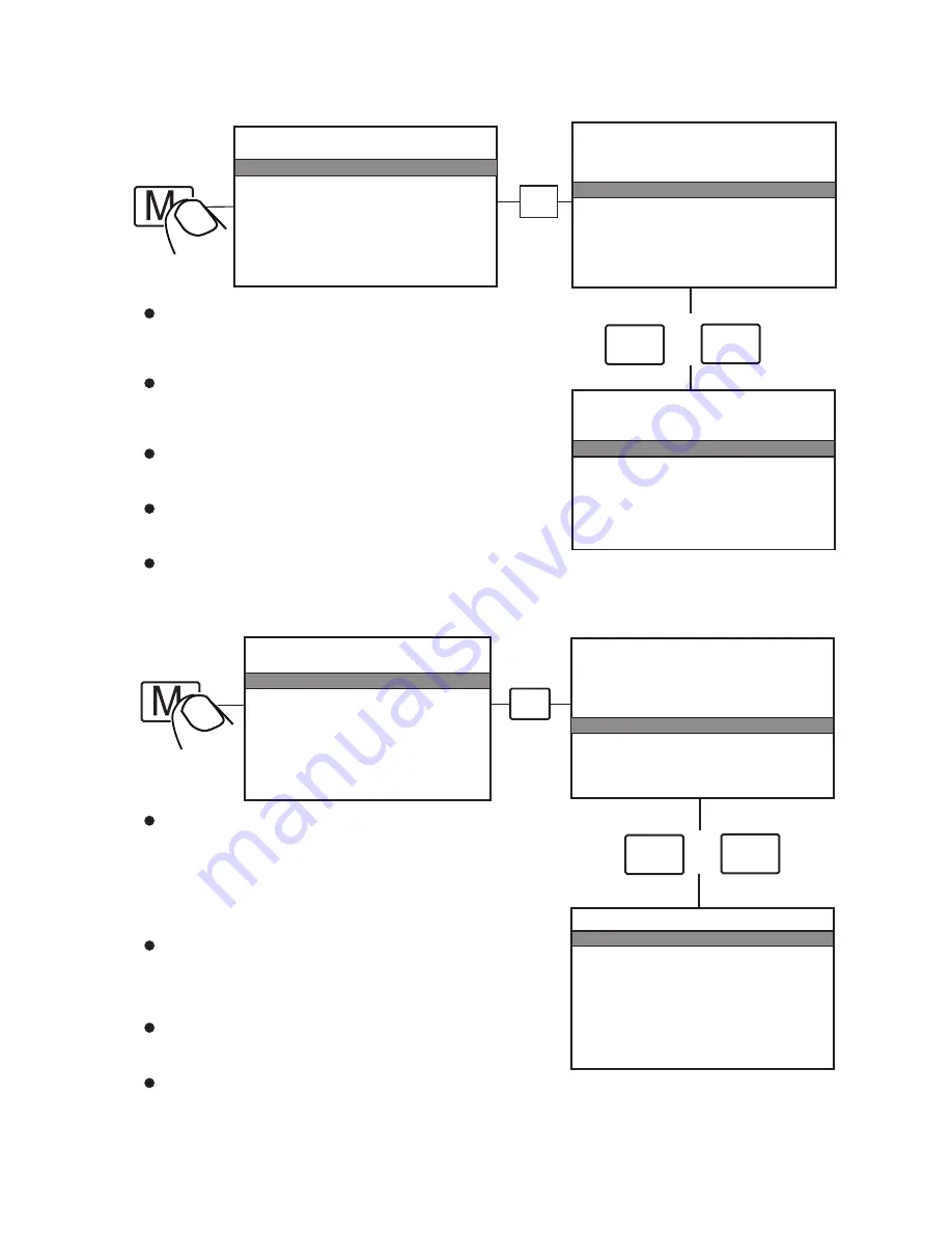
7.2 Trigger Setting


      MAIN MENU

OSD                                SETUP

SYSTEM                        SETUP

TRIGGER                      SETUP

TRIGGER                      PRIORITY

RESET                           ALL

CAMERA                        SETUP


      MAIN MENU

OSD                                SETUP

SYSTEM                        SETUP

TRIGGER                      SETUP

TRIGGER                      PRIORITY

RESET                           ALL

CAMERA                        SETUP


        MAIN MENU

OSD                                SETUP

SYSTEM                        SETUP

TRIGGER                      SETUP

TRIGGER                      PRIORITY

RESET                           ALL

CAMERA                        SETUP

     TRIGGER        SETUP

TURN IMAGE           SINGLE

REAR IMAGE           BACK

TRIGGER DELAY    03 SEC

SPLIT   SCREEN:

     LEFT                     LEFT

     RIGHT                  RIGHT

     AUDIO                  LEFT 


      MAIN MENU

OSD                                SETUP

SYSTEM                        SETUP

TRIGGER                      SETUP

TRIGGER                      PRIORITY

RESET                           ALL

CAMERA                        SETUP

OSD    SETUP

SCALE                          ON

INPUT  SCAN               OFF

BOUNDARY                 WHITE

LANGUAGE             ENGLISH

V19:E00A20130723

 (to be updated)


_

+

/

_

+

/

S

S

7.1 OSD Setting

SCALE: 

To turn on / off electronic distance label. When set as ON, 

electronic distance label will be displayed when rear view 

camera (camera 3) is activated.

INPUT SCAN: 

To turn on / off auto identification of camera inputs. 

When INPUT SCAN is set as ON, monitor will display

connected cameras and skip inputs not in connection.  

BOUNDARY: 

To set color of the separation line between camera inputs.

White, gray, black and uncolored are available.

LANGUAGE: 

To set OSD language. English, French, Dutch, Spanish, 

German and Italian are available.

SOFTWARE VERSION: 

To be updated at all times.

TURN IMAGE: 

To set the camera input(s) to be displayed when left-side camera 

(camera 1) / right-side camera (camera 2) is activated.When set 

as SINGLE, correspond camera input will be displayed when either 

camera is activated.When set as SPLIT,split image of left-side and 

rear view camera will be displayed when left-side camera is 

activated; split image of right-side and rear view camera will be 

displayed when right-side camera is activated.

REAR IMAGE: 

To set the camera input(s) to be displayed when rear view camera 

is activated. When set as BACK, the rear view camera will be 

displayed when activated. When set as TRIPLE,left-side, 

right-side and rear view camera will be displayed.

TRIGGER DELAY: 

To set the delaying time of video display when trigger 

signal goes off. Delaying time frame: 0-30 seconds.

SPLIT SCREEN: 

To set the camera input(s) to be displayed when “split”trigger wire 

is activated. LEFT / RIGHT is to set the camera input 

to be displayed on the left / right side of monitor screen.

AUDIO is to set the audio output from any of the four cameras.

Summary of Contents for VTM7003QMA

Page 1: ...7 COLOR LCD WATERPROOF QUAD MONITOR WITH TOUCH SCREEN Operating Instructions Please read this manual thoroughly before operating the unit and keep it for future reference V1 0 VTM7003QMA...

Page 2: ...ntents 3 Monitor Installation 5 Monitor Operations 7 Menu and Touch Screen Operations 8 Specifications 4 Connections 4 5 6 15 9 6 Remote Operations 7 1 Precautions 1 9 Troubleshooting 16 2 Accessories...

Page 3: ...er puncture scratch or use abrasive cleaning materials on this device 7 Do not place cables where they may be pinched or stepped on 8 Leave at least a 2 space between the monitor and walls cabinets or...

Page 4: ...ence of uninsulated dangerous voltage within the product s enclosure that may be of sufficient magnitude to constitute risk of electric shock to persons You are cautioned that any changes or modificat...

Page 5: ...ries may be different for different applications Special Notice U Support Bracket Center Mount Bracket Adapter Cable IR Remote Control Sun Shield AV and Power Supply Angle Adjustment Screws 4P Female...

Page 6: ...3 Monitor installation Center Mount Bracket 4...

Page 7: ...1 Blue Trigger 2 Green Trigger 3 Brown Trigger 4 Black Ground 4 Connections Camera 1 Yellow Split trigger Green Rec V output Yellow Live V output Red Power 11 5 1 1 AUX audio input 2 2 3 3 4 4 5 5 6 6...

Page 8: ...6 1 6 To increase decrease the volume and switch between values of each sub menu Menu selection and display mode single dual triple quad view PIP image selection Menu control button Jump key selector...

Page 9: ...ntrol or allow it to drop or wet Please align the remote control with the remote signal receiver window to operate get WARNING 6 Remote Operations 1 2 4 3 6 7 5 9 8 10 11 13 12 MODE SEL LANG REST AV D...

Page 10: ...n UP Menu selection up DN Menu selection and display mode single dual triple quad view PIP image selection P N PAL NTSC TV system selector Language selection LANG To restore factory settings REST AV V...

Page 11: ...s White gray black and uncolored are available LANGUAGE To set OSD language English French Dutch Spanish German and Italian are available SOFTWARE VERSION To be updated at all times TURN IMAGE To set...

Page 12: ...ing function When AUTOSCAN is set as ON monitor will automatically switch between connected camera inputs and quad image SCAN DELAY To set the switching time of AUTOSCAN Switching time frame 0 60 seco...

Page 13: ...menu not available in DVD VGA aux channel or when auto scan is on 4 Brightness increase decrease LEFT 1 1 2 3 4 LEFT RIGHT BACK 3 Touch vol IIIIIIIIIIIIIII 15 2 The previous display mode The display m...

Page 14: ...2 6 Menu selection up down 7 Switches between values of each sub menu Touch Touch The previous display mode MAIN MENU OSD SETUP SYSTEM SETUP TRIGGER SETUP TRIGGER PRIORITY RESET ALL CAMERA SETUP 5 aga...

Page 15: ...any two cameras displayed in multi viewing mode 7 4 4 Exchange picture locations of two cameras in dual triple viewing mode 1 displayed 1 hidden 7 4 5 7 4 6 LEFT BACK RIGHT Touch till areas darkended...

Page 16: ...he volume 7 4 8 7 4 7 Decrease the volume LEFT RIGHT Touch the right corner and slide downwards RIGHT LEFT VOL IIIIIIIIIIIII 13 LEFT RIGHT Touch the right corner and slide upwards RIGHT LEFT VOL IIIII...

Page 17: ...Max 25W Power Output to Camera Max 4 300mA 12V Power Supply 10V 32V Video Input 4 video inputs for camera peak value 1Vp p impedance 75 ohm 1 DVD input peak value 1Vp p impedance 75 ohm Audio Input 4...

Page 18: ...ected or the sound volume is turned off or set too low Check whether brightness and contrast are adjusted correctly Check whether the environmental temperature is too low Adjust the color settings The...

Page 19: ...nd not intended for use as substitutes for rear view mirror devices or for any other standard motor vehicle equipment required to be installed on vehicles by law Our products are no substitute for pro...

Page 20: ......

Reviews: