background image

6

7

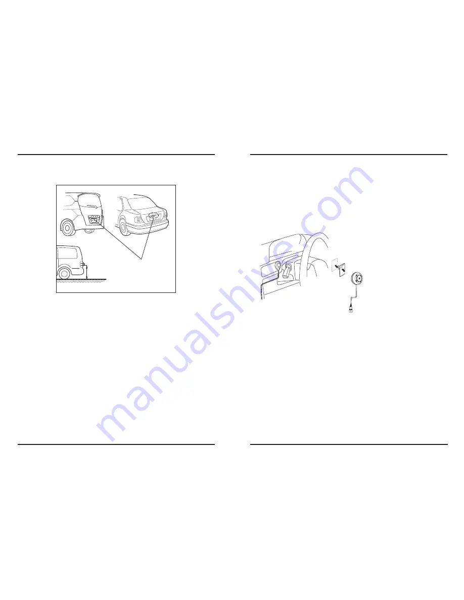
2. Recommended Installation Position

2-1 Examples of correct camera installation

2. Recommended Installation Position

2-2 Installing the Switch Unit

ˍGyŒŠ–””Œ•‹Œ‹Gp•š›ˆ““ˆ›–•GŒŽ›GaGZUY\›

  1. Decide the camera installation position.
  2. Clean the camera installation surface.

GGGGG|š•ŽGˆGŠ–””Œ™Šˆ““ Gˆˆ“ˆ‰“ŒGŠ“Œˆ•Œ™SGž—ŒG‹™›SG”–š›œ™ŒGˆ•‹G–“Gˆžˆ G™–”G›ŒG
GGGGGšœ™ˆŠŒG–•GžŠG›ŒGŠˆ”Œ™ˆGšG›–G‰ŒGˆ››ˆŠŒ‹U

  3. Mount the camera on the license plate.
  4. Fix the camera temporarily with screw.  
  5. Complete all of the required connections.
  6. Display the camera video.

GGGGGz–”ŒG‹Œ–G”–•›–™šG”ˆ Gšž›ŠGˆœ›–”ˆ›Šˆ““ G›–G›ŒGŒŸ›Œ™•ˆ“G‹Œ–G•—œ›Gœ•Š›–•UG
GGGGGm–™G‹Œ›ˆ“šSG™Œˆ‹G›ŒG•š›™œŠ›–•G”ˆ•œˆ“G–™G –œ™G‹Œ–G”–•›–™U

  7. Change the shift lever to the R (Reverse) range to view the image of the rear of the 
      vehicle.

GGGGGiŒ–™ŒGŒž•ŽG›ŒGŠˆ”Œ™ˆSGˆ——“ G›ŒG—ˆ™’•ŽG‰™ˆ’ŒGˆ•‹GŠ–Š’G›ŒGžŒŒ“šGš–G›ˆ›G›ŒG
GGGGGŒŠ“ŒGž““G•–›G”–ŒUGv›Œ™žšŒSGˆ•Gœ•ŒŸ—ŒŠ›Œ‹GˆŠŠ‹Œ•›G”ˆ G™Œšœ“›U

  8. Adjust the camera angle so that the rear part of the vehicle or the rear bumper is 
      visible at the bottom of the monitor screen.

GGGGG~Œ•Gˆ‹‘œš›•ŽG›ŒGŠˆ”Œ™ˆGˆ•Ž“ŒSG‰ŒGŠˆ™Œœ“G•–›G›–Gš›™Œ›ŠG›ŒGŠˆ”Œ™ˆGŠ–™‹U

  9. After adjusting the camera angle, tighten the retaining screws firmly.

GGGGGp•š—ŒŠ›G›ŒG™Œ›ˆ••ŽGšŠ™ŒžšGˆ›G›”ŒšUGpG›Œ Gˆ™ŒG“––šŒSG›Ž›Œ•G›Œ”G™”“ U

10.Perform the operations in “Camera Setting”. 

GGGGpGˆ•Gˆ‹‘œš›”Œ•›GšG•–›G—–šš‰“ŒG•G›ŒGŠœ™™Œ•›“ Gˆˆ“ˆ‰“ŒG™ˆ•ŽŒSGŠˆ•ŽŒG›ŒGŠˆ”Œ™ˆG
GGGG—–š›–•G‰Œ–™ŒG™Œ›™ •ŽU

11.Fix the camera firmly in position.

G

1. Clean the switch unit installation surface.

GGGGG|š•ŽGˆGŠ–””Œ™Šˆ““ Gˆˆ“ˆ‰“ŒGŠ“Œˆ•Œ™SGž—ŒG‹™›SG”–š›œ™ŒGˆ•‹G–“Gˆžˆ G™–”G›ŒG
GGGGGšœ™ˆŠŒG–•GžŠG›ŒGšž›ŠGœ•›GšG›–G‰ŒGˆ››ˆŠŒ‹U
G

 2. Attach velcro tape on the bottom of the switch unit and then attach it in an 
     easy-to-operate position, for example near the dashboard on the driver seat side.

Installation position

ଝଝଝ

Summary of Contents for VTL275HDL

Page 1: ...Rear View Camera puz y j pvuGthu hs w G G G G G G G G G G G U Model G sY oks G sZ oks G s W oks G s Y oks XZW Y TY...

Page 2: ...G G UGp G G G G G G G G G G G U G G UGk G G G G G G G U G G_UG G G G SG G G G G G G G G G G G GGGGG U G G UGk G G G G G G U XWUGk G G G G G G U XXUGk G G G G G G G U G To prevent damage to the produc...

Page 3: ...l or workmanship Vision Tech America Inc will repair or replace the entire product where each party will be responsible for one way shipping This limited warranty does not cover any physical damage to...

Page 4: ...e of the rear of the vehicle GGGGGi G G G SG G G G G G G G G G G G GGGGG G G G UGv SG G G G G U 8 Adjust the camera angle so that the rear part of the vehicle or the rear bumper is visible at the bott...

Page 5: ...ance the vehicle GG Gt G G G G G G G G G G G G G G G GGGG U GG Gi G G G G G G G G G G G G G G G G G GGGG G UGw G G G G G G G G G G G G GGGG G U 3 Wring Connections 4 Camera Setting 3 1 Basic Connectio...

Page 6: ...des 5 2 Features on off Viewing mode 6 Top view with parking lines Turning on and off the mirror imaging While the camera is on any of the viewing modes 1 through 6 press the LEFT button to turn on or...

Page 7: ...ter finish press the SET button to move onto the yellow lines While the yellow lines are blinking use the LEFT and RIGHT buttons to shrink or expand the lines Then press the SET button to move onto th...

Page 8: ...0mA LED On 1 3 7 progressive scan CMOS Progressive scan 720 x 480 AUTO 50dB AGC OFF 0 2Lux at F1 2 LED Off 0Lux at F1 2 LED On 0 005 r 0 45 a AUTO 1 30 1 30 000 Shutter Speed ON ON OFF ON OFF DNR ON O...

Reviews: