background image

8


Description of the implement 


Jelly power pack Edition 09.09 
 

3.2 

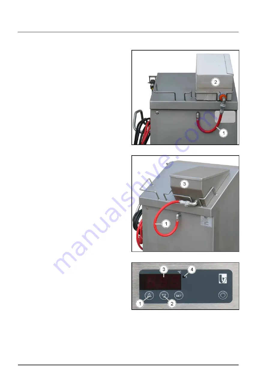
Functional description 

A  pneumatically  driven,  diaphragm  controlled  agent-
feed-pump  sucks  the  cold  jelly  via  the  suction-hose 
(1)  out  off  the  one-way  jelly  container  (Bag  in  Box 
(BIB))  (2)  or  the  jelly  container  (3)  (special 
equipment). 

Then  the  sucked  off  jelly  is  delivered  via  the  agent-
feed-pump  to  the  flow-heater.  Inside  the  flow-heater 
the jelly is heated to the set processing temperature. 


The  processing  temperature  can  be  set  via  UP-  and 
DOWN-keys (1 and 2) between 

25.0 and 93.0°C

The  temperature  display  (3)  shows  the  actual 
system-temperature 

in 

Degree 

Celsius. 

The 

implement  is  ready  for  use  when  the  red 
temperature-control light (4) has gone out. 


Summary of Contents for Jelly power pack

Page 1: ...Hotline In case of malfunction please call our Hotline No Tel 49 0 54 51 96 37 38 Fax 49 0 54 51 96 37 35 Before starting operation carefully read and adhere to this instruction manual and the safety...

Page 2: ...4 3 General requirements on the compressed air source 14 4 4 Connecting the implement to an external compressed air source 15 4 5 Connect the one way jelly container BIB 16 4 6 Switching the implemen...

Page 3: ...angers Storing the instruction manual Always keep this instruction manual with the machine The instruction manual must always be at hand Transport and take over Only transport the implement standing o...

Page 4: ...able These have been available to the user at the latest since conclusion of the contract Warranty and liability claims for personal injury or damage to property shall be excluded if they result from...

Page 5: ...labour medical regulations and hygienic precautions Keep all safety and danger hints on the implement readable and clean and exchange if necessary 2 6 Training the personnel Only trained and advised...

Page 6: ...unscrewed beforehand On completion of maintenance work check the function of all safety devices 2 11 Modifications Never change anything on the implement do not add anything to the implement and do no...

Page 7: ...olt 50 Hz 2 Compressed air connection for external compressed air source The inlet air pressure of the external compressed air system may not exceed 6 bar 3 Agent hose 4 Spray pressure setting 5 Spray...

Page 8: ...jelly container 3 special equipment Then the sucked off jelly is delivered via the agent feed pump to the flow heater Inside the flow heater the jelly is heated to the set processing temperature The...

Page 9: ...nded spraying Hold the spray gun at a distance of approx 10 cm above the product to be sprayed and pull the trigger lever 4 Depending on the size of the surface to be sprayed use the flat jet or round...

Page 10: ...pressure PS 6 bar Minimum maximum permissible operating temperature TS 2 C to 50 C Maximum humidity 90 External compressed air Compressed air output 90 litres min 6 bar Compressed air connection Nomin...

Page 11: ...se up to the spray gun with spray gun with heat reflecting casing with temperature control controlled heat adjustment with pneumatically driven diaphragm controlled agent feed pump with low maintenanc...

Page 12: ...tric circuit is protected by fuse with 16 Ampere If so connect the implement with the aid of the CEE power plug to the power supply 4 1 Operation Only operate the implement with all guards fully funct...

Page 13: ...acid containing product Silicone textile casing for stability Resistance wires for heating Protect the agent hose against damage from sharp edged objects Danger of injury from discharging hot agent I...

Page 14: ...rough of the pressure vessel If your present compressed air source does not meet the above requirements we recommend you use our three stage special filter unit The three stage special filter unit con...

Page 15: ...nts on the compressed air source page 14 During the spraying procedure the implement must be permanently connected with the external compressed air source as otherwise spraying will not be possible Th...

Page 16: ...container 3 Place the jelly containers into the holder 5 so that the adapter 4 is located below Connect the adapter 4 and the suction hose 6 via the coupling plug 7 For this simply push the socket 8 f...

Page 17: ...up to the prior set processing temperature The temperature display 3 shows the current system temperature The implement is ready for operation if the red temperature control light 2 goes out If the i...

Page 18: ...ion forward or backward By pressing the same key again the display continuously moves until the key is released After having obtained the desired processing temperature first release the UP or DOWN ke...

Page 19: ...ning knob 1 To set the spraying pressure slightly pull out the turning knob 1 and turn it into the desired direction To increase the spraying pressure turn the turning knob clockwise To reduce the spr...

Page 20: ...round jet nozzle 1 for small and round products red flat jet nozzle 2 for large areas and cake tins Exchanging the agent nozzle Secure the spray gun by means of the locking device 1 against unintende...

Page 21: ...ft and right hand swivelling movements above the bakery products Spraying the product Unlock the spray gun locking device Hold the spray gun at a distance of approx 10 cm directly above the bakery pro...

Page 22: ...the material channel would be the result when the system goes on heating without material Damage due to material channel which have not been flushed emptied by spraying will not be accepted as claims...

Page 23: ...al break Connect the implement to an external compressed air source Take the spray gun out of the retainer Protect the spray gun against unintended spraying by turning the locking device After the age...

Page 24: ...y devices Most malfunctions are caused by contamination of the compressed air and the agent to be processed To clean the implement only use clear water clear water with a maximum water temperature of...

Page 25: ...e agent channel might be the result Connect the suction hose 1 and the cleaning hose 2 via the coupling plug 3 Dip the cleaning hose 2 into a bucket with water Actuate the spray gun and spray the wate...

Page 26: ...he agent nozzle using hot water Re insert the agent nozzle into the bayonet cap Screw the bayonet cap back onto the spray gun 5 3 Maintenance 5 3 1 Weekly Check the hinged joint 1 between the spray gu...

Page 27: ...connected to the electric power supply and not pressurised Switch off the implement Pull the power supply plug out of the socket Actuate the spray gun and thus discharge the residual air pressure out...

Page 28: ...pen the implement housing before you remedy leaking compressed air connections exchanging the agent hose exchanging the agent feed pump In case of queries please do not hesitate to contact our after s...

Page 29: ...mpressed air connections once a week Pressurise the system Switch off the implement and pull the CEE power plug from the socket Open the implement housing Refer to chapter Opening and closing the impl...

Page 30: ...plug from the socket Separate the implement from the external compressed air source Actuate the spray gun and thus discharge the residual air pressure out off the system Open the implement housing Ref...

Page 31: ...lement Pull the CEE power plug from the socket Separate the implement from the external compressed air source Actuate the spray gun and thus discharge the residual air pressure out off the system Open...

Page 32: ...hermostat has been tripped Let the implement cool down Temperature control defective Contact the maintenance service Temperature does not rise Microprocessor defective Contact the maintenance service...

Page 33: ...and maintaining 33 Jelly power pack Edition 09 09 Fault Cause Remedy The jelly is not liquid Check the jelly Spray gun only sprays air The jelly is warm and jellied already inside the jelly container...

Page 34: ...9 09 6 Spare part list Item Article No Designation Quantity 1 3329 Spray gun body bayonet 1 2 3330 Seal kit bayonet completely 1 3 3331 Bayonet cap 607 1 4 3332 Bayonet cap 733 for round jet nozzles 1...

Page 35: ...ly power pack Edition 09 09 Article No Designation Component 2046 Agent feed pump 1409 Silicone hose blue 6 mm yard ware 970 Bracket 13 3 VA 1655 hinged joint VA 963 Pressure regulator MRS 08 0 9 bar...

Page 36: ...ck Edition 09 09 Article No Designation Component 1998 Plug in nipple mes 1 4 aG NW 7 2 type 26 1584 Round jet nozzle yellow 1587 Flat jet nozzle yellow 1585 Round jet nozzle green 1588 Flat jet nozzl...

Page 37: ...Spare part list 37 Jelly power pack Edition 09 09 Article No Designation Component 1586 Flat jet nozzle red...

Page 38: ...38 Circuit diagrams Jelly power pack Edition 09 09 7 Circuit diagrams...

Page 39: ...Circuit diagrams 39 Jelly power pack Edition 09 09...

Page 40: ...40 Circuit diagrams Jelly power pack Edition 09 09...

Page 41: ...Circuit diagrams 41 Jelly power pack Edition 09 09...

Page 42: ...42 Circuit diagrams Jelly power pack Edition 09 09...

Page 43: ...less the damage can be traced back to a fault on our side Impure compressed air or compressed air being wet or containing foreign particles Sealings and hoses All firm or moving components which get i...

Page 44: ...of construction Capacity Machine number is in conformity with the provisions of the following EC directives EC Machinery Directive 98 37 EC EC Low Voltage Directive 2006 95 EC EC Electromagnetic Compa...

Reviews: