BOXLIGHT CP-775i User Manual Download Page 8

ENGLISH-7

ENGLISH

II

II

N

N

N

N

S

S

S

S

T

T

T

T

A

A

A

A

L

L

L

L

L

L

L

L

A

A

A

A

T

T

T

T

II

II

O

O

O

O

N

N

N

N


((

((

c

c

c

c

o

o

o

o

n

n

n

n

tt

tt

ii

ii

n

n

n

n

u

u

u

u

e

e

e

e

d

d

d

d

))

))

• Before connecting, read instruction manuals of the devices to be connected, and make sure that the

projector is compatible with the device. 
• Secure the screws on the connectors and tighten.
• For some RGB input modes, the optional Mac adapter is necessary.
• To select the DVI input, the comuter may need some settings. See the manuals of the computer for details.
• Some computers may have multiple display screen modes. Use of some of these modes will not be possible
with this projector.
• Refer to the “TECHNICAL” section for the pin assignment of connectors and RS-232C communication data.
• When the DVI terminal is used, the RGB OUT terminal may not function.

NOTE

CAUTION • Incorrect connecting could result in fire or electrical shock.
Please read this manual and the separate “SAFETY INSTRUCTIONS”.

• Before connecting, turn off to all devices to be connected, except for the USB
cable.
• The cables may have to be used with the core set to the projector side. Use the
cables which are included with the projector or specified.
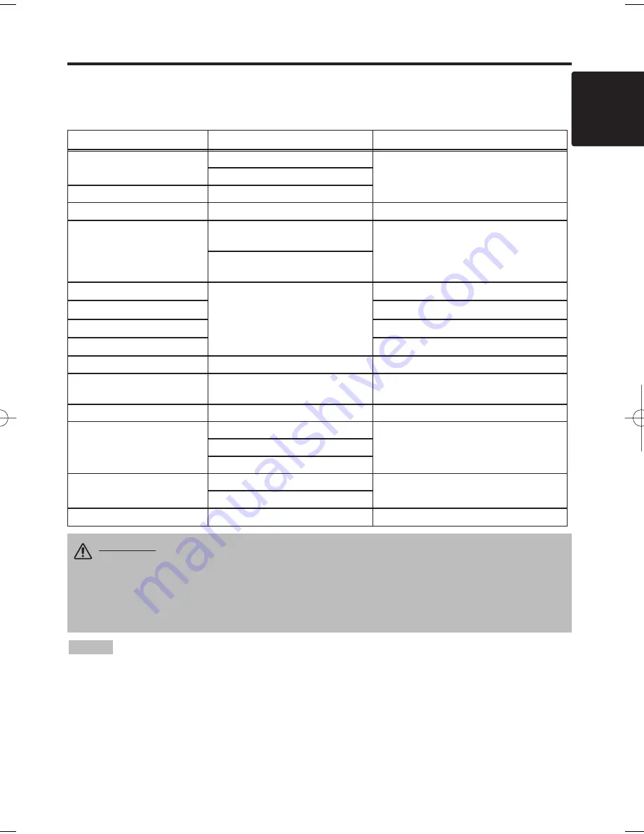
Cabling

Refer to the table below for connecting each terminal of the projector to 

a

 device.

Table 2. Cabling

Function

Terminal

Cable

RGB input

RGB IN 1

RGB cable 

with D-

sub 15-pin shrink jack 

and inch thread 

screws

RGB IN 2

RGB output

RGB OUT

DVI input

DVI

DVI cable with inch thread screws

Audio input
(from the computer)

AUDIO IN 1

(interlocked with RGB IN 1 or DVI)

A

udio cable with stereo mini jack

AUDIO IN 2

(interlocked with RGB IN 2)

PS/2 mouse control

CONTROL

PS/2 mouse cable

ADB mouse control

ADB mouse cable

Serial mouse control

Serial mouse cable

RS-232C communication

RS-232C cable

USB mouse control

USB

USB cable

S-video input

S-VIDEO IN

S-

V

ideo cable 

with mini DIN 4-pin 

jack

Video input

VIDEO IN

V

ideo/

A

udio cable

Component video input

COMPONENT VIDEO Y

C

omponent 

V

ideo cable

COMPONENT VIDEO C

B

/P

B

COMPONENT VIDEO C

R

/P

R

Audio input
(from video equipment)

AUDIO IN L

V

ideo/

A

udio cable 

or A

udio cable with RCA jack

AUDIO IN R

Audio output

AUDIO OUT

A

udio cable with stereo mini jack

01CP-775i  02.1.29 10:25 AM  ページ 7

Summary of Contents for CP-775i

Page 1: ...entamente il manuale d sitruzioni in modo tale da poter comprendere quanto riportato ai fini di un corretto utilizzo del proiettore MANUAL DE USUARIO Lea cuidadosamente este manual del usuario para po...

Page 2: ...Message 20 Table 10 Indicators Message 21 Table 11 Symptom 22 Table 12 Specifications 23 For TECHNICAL and REGULATORY NOTICE see the end of this manual The information in this manual is subject to cha...

Page 3: ...iese Bedienungsanleitung zugunsten der korrekten Bedienung aufmerksam MANUEL D UTILISATION Nous vous recommandons de lire attentivement ce manuel pour bien assimiler le fonctionnement de l appareil MA...

Page 4: ...r Filter and Intake for the Cooling Fan INPUT Button LAMP Indicator TEMP Indicator POWER Indicator RESET Button MENU Button Ventilation Openings exhaust REAR RIGHT VIEW OF THE PROJECTOR Terminal Panel...

Page 5: ...Button MOUSE RIGHT Button Used to click the right mouse button RESET Button Used to click the right mouse button FREEZE Button MUTE Button PinP Button KEYSTONE Button VOLUME Button These functions wor...

Page 6: ...Use only the specified batteries with this remote control transmitter Also do not mix new and old batteries This could cause battery cracking or leakage which could result in fire or personal injury...

Page 7: ...to the screen 10 Table 1 Installation Reference a CAUTION Install the projector in a suitable environment according to instructions of the accompanying manual SAFETY INSTRUCTIONS and this manual When...

Page 8: ...l devices to be connected except for the USB cable The cables may have to be used with the core set to the projector side Use the cables which are included with the projector or specified Cabling Refe...

Page 9: ...ay is a system configured with peripheral equipment including a computer display and an operating system This projector is recognized as a plug play monitor Use the standard display drivers Plug play...

Page 10: ...the POWER indicator is blinking 2 The system assumes the Standby mode when cooling is complete and the POWER indicator ceases blinking and changes to orange Check that the indicator is orange and set...

Page 11: ...NIFY mode with a video signal is input After approximately 10 seconds of inactivity the icon is extinguished and the POSITION mode is cleared automatically and buttons may operate as the mouse control...

Page 12: ...U SELECT Select Menu Type Press the MENU SELECT button Allows the user to select the normal menu or the single menu Only the selected item is displayed on the single menu and other items are displayed...

Page 13: ...I VIDEO S VIDEO COMPONENT BRIGHT Adjustment Dark Light CONTRAST Adjustment Weak Strong V POSIT Adjustment Down Up H POSIT Adjustment Left Right H PHASE Adjustment Left Right Adjust to eliminate flicke...

Page 14: ...menu This operation requires approximately 10 seconds It may not function correctly with some input signals Pressing the AUTO button in this case may correct this problem This function is the same as...

Page 15: ...fixed screen is displayed TURN OFF displays the blue screen When MyScreen or ORIGINAL is selected the screen is going to the black after several minutes MyScreen Set MyScreen Mode Select the EXECUTE...

Page 16: ...ear AUTO OFF Select STOP 0 min with the button When STOP is selected the system does not enter the standby mode even if no signal is received SYNC ON G SYNC ON G Valid Select TURN ON with the button S...

Page 17: ...al is input My Screen is a mode that the customer customized screen is displayed This is the blue screen at the factory setting Refer to the description of MyScreen below ORIGINAL is a mode that the f...

Page 18: ...mperature Before replacing the lamp switch power OFF wait approximately 20 minutes and switch power ON again If the LAMP indicator is still red replace the lamp NOTE WARNING For disposal of used lamp...

Page 19: ...he Lamp Timer Reset the lamp timer after replacing the lamp When the lamp has been replaced after the LAMP indicator is red or the CHANGE THE LAMP message is displayed complete the following operation...

Page 20: ...h CAUTION Switch power OFF and remove the power cord from the power outlet before beginning maintenance work Please read the separate SAFETY INSTRUCTIONS thoroughly to ensure that maintenance is perfo...

Page 21: ...set the lamp timer after replacing the lamp CHANGE THE LAMP AFTER REPLACING LAMP RESET THE LAMP TIME THE POWER WILL TURN OFF AFTER 0 hr The usage time of lamp is about to reach Power will be switched...

Page 22: ...ks Lights red Blinks red Turns off Lamp or lamp cover is not found or hasn t been fitted in correctly Switch power OFF and wait for 45 minutes until the equipment cools Check fitting of the lamp and l...

Page 23: ...resent but no audio The projector is not correctly connected Connect correctly 7 8 The volume is set to minimum Press VOLUME on the remote control or display the menu screen and adjust the volume 11 1...

Page 24: ...DC 150 1200 mV AC 1 56 Vp p TTL Level Positive Negative AUDIO IN RGB1 200mVrms 50 k max 3 0Vp p Stereo mini jack DVI RGB2 Video signal input VIDEO IN 1 0Vp p 75 terminator RCA jack S VIDEO IN Brightne...

Page 25: ...Product WARRANTY LIMITATION AND EXCLUSION BOXLIGHT CORPORATION shall have no further obligation under the foregoing limited warranty if the Product has been damaged due to abuse misuse neglect acciden...

Page 26: ...Printed in Japan QR52531...

Reviews: