BOXER C 24 Installation And Servicing Download Page 43

43

BOXER


combination boiler - 

Installation and Servicing

SERVICING

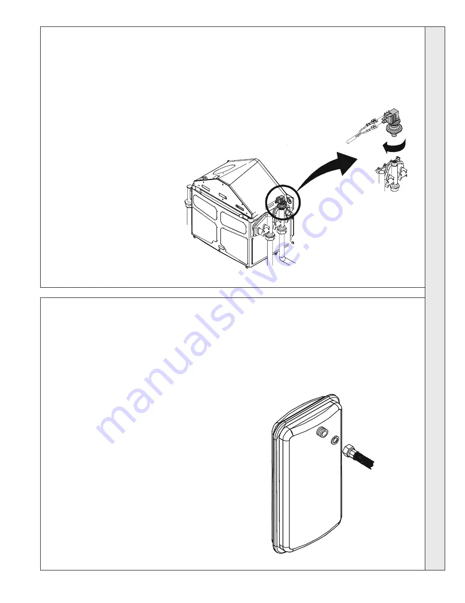
68 LOW WATER SWITCH REPLACEMENT

1.

Refer to Frame 49.

2.

Remove the casing. Refer to Frame 41.

3.

Drain the boiler. Refer to Frame 44.

4.

Disconnect the electrical lead from the low

water switch.

5.

Unscrew the low water switch nut and

remove the switch.

6.

Fit the new 

low water switch

 and re-

assemble in reverse order, using a suitable

sealant material.

7.

Refill the boiler. Refer to Frames 4 and 28.

5

4

69 EXPANSION VESSEL REPLACEMENT

1.

Refer to Frame 49.

2.

Remove the casing. Refer to Frame 41.

3.

Drain the boiler. Refer to Frame 44.

4.

Undo the union nut on the vessel water flexible connection

pipe.

5.

Remove the expansion vessel. 

Refer to Frame 43.

6.

Fit the new expansion vessel using the new sealing

washer provided.

7.

Re-assemble in reverse order.

8.

Refill the boiler. Refer to Frames 4 and 28.

4

Note.

If preferred, and for convenience, a new expansion vessel

may be installed on the return pipework elsewhere in the

heating system providing it ensures equivalent system

protection.

SER

VICING

All manuals and user guides at all-guides.com

Summary of Contents for C 24

Page 1: ...fety and performance specification we require Do not use reconditioned or copy parts that have not been clearly authorised by the manufacturer installation and servicing C24 C28 Combination boiler You...

Page 2: ...ft3 Key to symbols I E Ireland GB United Kingdom Countries of destination PMS Maximum operating pressure of water C12 C32 C52 A room sealed appliance designed for connection via ducts to a horizontal...

Page 3: ...Gas only G C Appliance No 47 348 22 BOXER C 24 G C Appliance No 47 348 23 BOXER C 28 PI No 0049AU2867 BOXER C 24 0049AU2949 BOXER C 28 Destination Countries GB IE NOTE TO THE INSTALLER LEAVE THESE IN...

Page 4: ...in appropriate places Pipework from the boiler is routed downwards as standard but may be routed upwards behind the boiler using the stand off frame supplied in a separate kit OPERATION With no deman...

Page 5: ...y the local authority For electrical safety reasons there must be no access available from the back of the boiler The boiler must not be fitted outside Timber Framed Buildings If the boiler is to be f...

Page 6: ...be used inside the building the space in which the boiler is to be installed must be at least wide enough to accommodate the tool Front clearance The minimum front clearance when built in to a cupboa...

Page 7: ...he air vents care must be taken to avoid the freezing of pipework GAS SUPPLY The local gas supplier should be consulted at the installation planning stage in order to establish the availability of an...

Page 8: ...oint of connection to the mains should be readily accessible and adjacent to the boiler 3 SYSTEM REQUIREMENTS Central Heating Safety valve setting bar 3 0 Vessel charge pressure bar 0 75 to 1 System p...

Page 9: ...tap supplied from a service pipe under mains pressure Where the mains pressure is excessive a pressure reducing valve must be used to facilitate filling i Thoroughly flush out the whole system with co...

Page 10: ...Marlowe Way Croydon Surrey CRO 4XS Tel 0870 5601 5000 Sentinel Division Notes 1 It is most important that the correct concentration of the water treatment product is maintained in accordance with the...

Page 11: ...11 BOXER combination boiler Installation and Servicing INSTALLATION 8 BOILER ASSEMBLY Exploded View INSTALLATION All manuals and user guides at all guides com a l l g u i d e s c o m...

Page 12: ...7 2 0 28 17 1 3 7 6 5 3 2 6 7 2 16 E 7 326 7 2 1 2 7 8 8 7 2 0 5 1 2 1 7 17 5 2 7 2 6 6 7 5 80 5 1 5 029 7 0 3 7 520 7 2 2 32 176 2 9 7 1 8 175 1 2 5 21 7 5 2 66 6 7 1 25 217 25 5 6 6 2 1 25 7 2 8 2 2...

Page 13: ...g to avoid damage 12 DETERMINING THE FLUE LENGTH AND FLUE PACKS REQUIRED Notes 1 The flue duct MUST be inclined at 1 5 degrees to the horizontal to not allow the rain come into the boiler 2 If the boi...

Page 14: ...les with center to center distance of 392 mm 15 7 16 c The position of the flue duct hole Note Mark the centre of the hole as well as the circumference 4 Remove the template from the wall 14 WALL MOUN...

Page 15: ...tted stand off kit 1 Measure and note wall thickness X Refer to Frame 12 2 Add 90 mm 3 9 16 to dimension X and measuring from the groove cut the outer tube only 3 To ensure the tube is cut square mark...

Page 16: ...safety drain outlet using a pressure fitting 15 mm O dia Service connections may be made now before mounting the boiler If required refer to Frames 24 to 27 or b Use stand off kit To allow pipework t...

Page 17: ...sed secure the support bracket using the spacer bracket and long wood screw Note When no extension duct is used the flue restrictor supplied in hardware pack A must be fitted Flue restrictor 20 FLUE E...

Page 18: ...d 7 Cut to length at the right size the external duct and cut the internal one 20 mm longer 8 De burr the metal edges 22 FITTING THE KIT General Notes 1 Fitting the Piping Frame top entry pipework is...

Page 19: ...CONNECTIONS Note The flow regulator and the filter are mounted internal of the boiler It should be inspected to ensure no blockage is evident See frame 65 Isolating valve shown in the open position 2...

Page 20: ...IMPORTANT when filling a The cap on the automatic air vent refer to Frame 64 MUST be loose at all times When filling there may be a slight water leak from the vent therefore electrical connections sh...

Page 21: ...n the temperature detected by the CH sensor is below 5 C the boiler is put into operation till the CH sensor detects a temperature off 15 C The frost protection electronic system is operating only if...

Page 22: ...nection Y Y 2YHUKHDW WKHUPRVWDW EN EU E EN RU E EU Z J J J EN J E EU J EU E JU U Z Z RU Z J Z Z Z Z EU Z EU U U E EU J EU E 0DLQV VXSSO 9 3XPS ODPH GHWHFWLRQ HOHFWURGH 0DLQV VZLWFK DQ LU SUHVVXUH VZLW...

Page 23: ...lation 1 The whole of the gas installation including the meter should be inspected and tested for soundness and purged in accordance with the recommendations of BS 6891 2 Purge air from the gas instal...

Page 24: ...ler On Off switch L Inlet pressure test point M Burner pressure test point N CH flow O DHW outlet P Gas inlet Q DHW inlet R CH return S Pressure gauge Control panel The user panel is equipped with two...

Page 25: ...ed by the above method further adjustment can be made using the MIN GAS potentiometer on the PCB refer to Frame 61 25 Check the new setting pressure Switch the boiler OFF then ON to check the pressure...

Page 26: ...ly central heating if there is a request for it Make the following checks for correct operation in DOMESTIC HOT WATER DHW MODE 1 With no call for CH or DHW the boiler is in stand by mode Only the main...

Page 27: ...lain the function of the boiler fault mode Emphasise that if a fault is indicated the boiler should be turned off and a registered local heating installer consulted 6 Explain and demonstrate the funct...

Page 28: ...need be taken If not proceed to Step 3 but see note above 3 Switch OFF the electrical supply 4 Remove the casing refer to frame 41 5 Remove the expansion vessel and vertical protection shield refer to...

Page 29: ...B remove and place on one side 3 Release the four fixing clamps on the upper and lower positions 2 2 C 4 Lift and remove casing D 5 Place the removed casing to one side to avoid damage A B C C D 42 CO...

Page 30: ...the protection shield and hang it on the frame bottom 4 Remove the two clips retaining the vertical protection shield and remove it only for 24 kW 5 Disconnect the wiring from the ignition transforme...

Page 31: ...oceeding to check operation of the boiler 5 drain point 5 45 FAN ASSEMBLY REMOVAL AND CLEANING 1 Remove the casing refer Frame 41 2 Disconnect the electrical leads from the fan 3 Undo the retaining sc...

Page 32: ...Undo and remove the 2 clips assembling the combustion chamber 2 Remove the combustion chamber 3 Disconnect the leads from ignition and ionisation electrodes including the earth lead 4 Unscrew the nut...

Page 33: ...Re assemble in reverse order 3 49 REPLACEMENT OF COMPONENTS GENERAL When replacing ANY component 1 Isolate the electricity supply 2 Turn off the gas supply 3 Remove the casing refer to Frame 41 4 If...

Page 34: ...33 40 5242 4300 50 3548 2945 60 2459 2063 70 1740 1475 80 1256 1075 90 923 797 100 690 600 TABLE OF RESISTANCE VALUES AS A FUNCTION OF THE TEMPERATURE OF THE SENSORS 51 FAN REPLACEMENT 1 Refer to Fram...

Page 35: ...nscrew the injectors 9 Fit the new injectors complete with copper gaskets 10 Re assemble in reverse order Note Check that all of the injectors have been replaced and security tightened 7 8 9 6 6 52 VE...

Page 36: ...the burner from the combustion chamber 8 Fit the new burner and re assemble in reverse order using a new gasket 6 6 6 7 55 OVERHEAT THERMOSTAT REPLACEMENT 1 Refer to Frame 49 2 Remove the casing Refe...

Page 37: ...57 HEAT EXCHANGER REPLACEMENT 1 Refer to Frame 49 2 Remove the casing Refer to Frame 41 3 Remove the expansion vessel and shield air guide Refer to Frame 43 4 Unscrew 3 screws and remove front panel...

Page 38: ...to Frame 49 2 Remove the casing Refer to Frame 41 3 Remove the expansion vessel and shield air guide Refer to Frame 43 4 Isolate and drain the DHW and CH circuits Refer to Frame 44 5 Unscrew the two D...

Page 39: ...Refer to Frame 35 11 Check the operation of the boiler and adjust the maximum and minimum pressures as necessary Refer to Frame 35 4 5 6 8 7 61 PCB REPLACEMENT 1 Refer to Frame 49 2 Remove the casing...

Page 40: ...EMENT 63 PRESSURE GAUGE REPLACEMENT 1 Refer to Frame 49 2 Remove the casing Refer to Frame 41 3 Remove the expansion vessel and shield air guide Refer to Frame 43 4 Drain the boiler Refer to Frame 44...

Page 41: ...r to Frame 44 4 For BOXER C 24 Unscrew the air vent from the CH return assembly and remove it For BOXER C 28 Pull out the air vent clip from the CH return assembly and pull up the air vent head 5 Fit...

Page 42: ...ump head 7 Remove the pump head 8 Fit the new pump head 9 Re assemble in reverse order 10 Refill the boiler Refer to Frames 4 and 28 5 6 67 AIR PRESSURE SWITCH REPLACEMENT 1 Refer to Frame 49 2 Remove...

Page 43: ...4 and 28 5 4 69 EXPANSION VESSEL REPLACEMENT 1 Refer to Frame 49 2 Remove the casing Refer to Frame 41 3 Drain the boiler Refer to Frame 44 4 Undo the union nut on the vessel water flexible connectio...

Page 44: ...ch and re assemble in 5 6 6 71 IGNITION TRANSFORMER REPLACEMENT 1 Refer to Frame 49 2 Remove the casing Refer to Frame 41 3 Remove the expansion vessel and shield Refer to Frame 43 4 Disconnect the el...

Page 45: ...T NO ARE THE SELECTOR SWITCH PROGRAMMER AND ROOM STAT ALL CALLING FOR HEAT NO REPAIR OR REPLACE FAULTY WIRING OR THERMISTOR YES TOP UP THE SYSTEM PRESSURE VIA THE FILLING DEVICE TO AT LEAST 1 bar YES...

Page 46: ...FAN RUN IS THERE 230 VacAT THE PUMP CONNECTION FREE THE SPINDLE USING A SCREWDRIVER OR REPLACE THE PUMP IS THE FLAME FAILURE LED ILLUMINATED REMOVE THE PUMP NUT DOES THE IMPELLOR SPIN FREELY IS THERE...

Page 47: ...ERATE TICKING SOUND REPAIR OR REPLACE FAULTY WIRING RECTIFY WIRING FAULT REPLACE FAULTY PCB DOES THE BURNER LIGHT ENSURE THE ELECTRODE LEAD IS CONNECTED UNDAMAGED AND NOT SHORTED TO EARTH ENSURE THE E...

Page 48: ...R THERMISTOR REPLACE FAULTY PCB ENSURE THERE IS SUFFICIENTWATER PRESSURE AND THE SUPPLY PIPE ISADEQUATE CLEAN INLET FILTER AND FLOWSWITCH REPLACE FAULTY FLOWSWITCH IF NECESSARY REPAIR OR REPLACE FAULT...

Page 49: ...AULTY GAS VALVE FAULTY THERMISTOR THIS HAS NOW BEEN REPLACED IS THE DHW TEMPERATURE SATISFACTORY REPLACE FAULTY THERMOSTATIC ELEMENT IN 3 WAY VALVE RECTIFY EXTERNAL SYSTEM FAULT DOES THE BURNER EXTING...

Page 50: ...Head 24 kW 1 172411 Pump Head 28 kW 1 172412 9 Pressure gauge 1 172413 10 Control panel 1 172416 11 Fascia 1 172415 12 Automatic air vent 24 kW 1 172417 Automatic air vent 28 kW 1 172418 16 Pressure...

Page 51: ...on boiler Installation and Servicing SHORT LIST OF PARTS 87 SHORT PARTS LIST 1 3 5 6 7 8 9 12 12a 10 11 16 20 28 43 17 27 26 21 48 40 39 33 31 30 29 All manuals and user guides at all guides com a l l...

Page 52: ...ore reserved to vary specification without notice The Ideal Boilers Technical Training Centre offers a series of first class training courses for domestic commercial and industrial heating installers...

Reviews: