Boulder 2010 Owner'S Manual Download Page 7

GETTING STARTED

INTRODUCTION

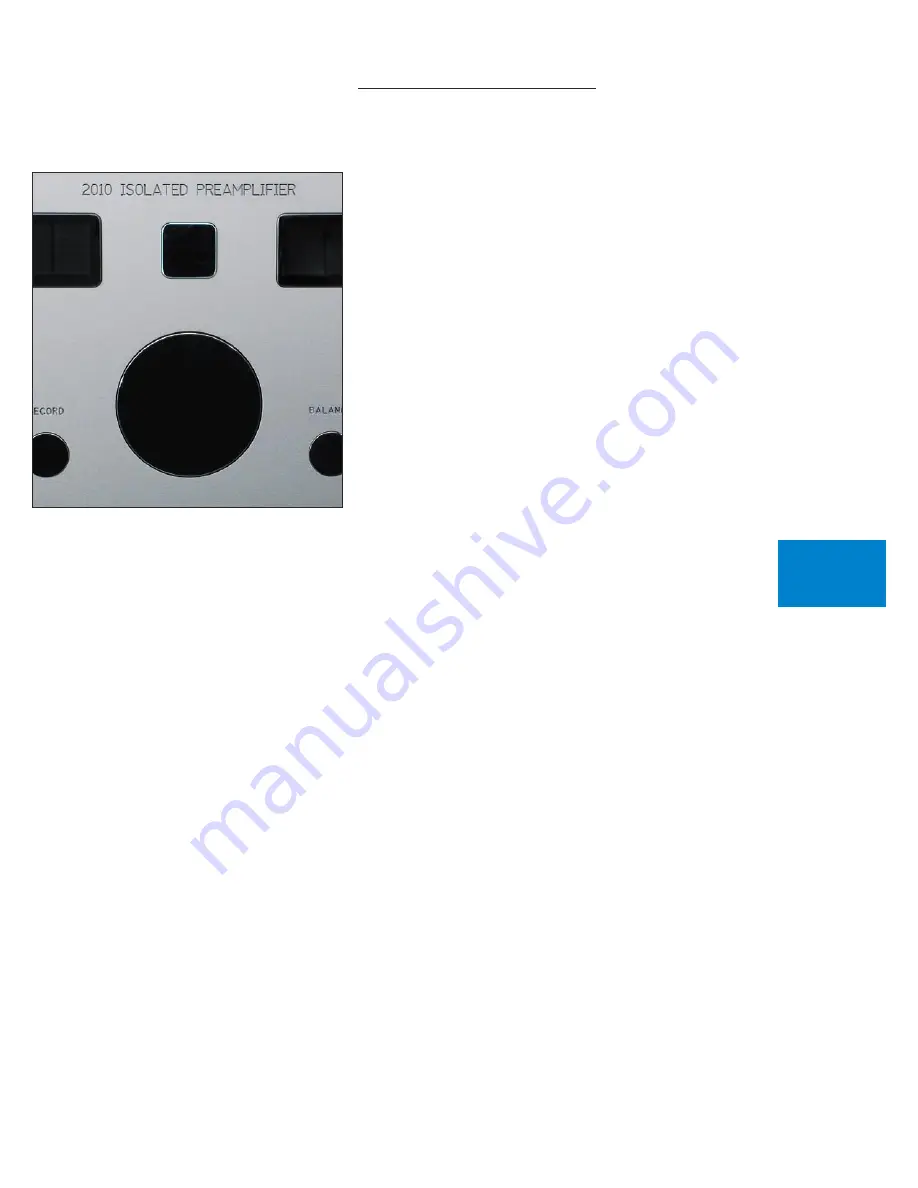
Congratulations on your selection of the Boulder 2010 Preamplifier. 

We at Boulder Amplifiers are certain it will provide years of listening 

pleasure.

BEFORE YOU START

To get started listening, you only need to connect the 2010 as you 

would any other preamplifier and the power supply as on page 1-3, but 

you should take note of the following.

WARNING: The polished volume control is attractive and because it 

is optical and has no stops, it is really tempting to just spin it around. DO 

THIS ONLY WITH THE POWER OFF! It must be given the respect you 

would any other volume control with its ability to get loud very quickly. 

By the time you have turned it up to -40.0 dB with a source turned on, 

you should be hearing some music. If not, don’t proceed any louder until 

you have solved the problem. See troubleshooting section.

For the 2010 to work properly, the Boulderlink’s MASTER/SLAVE 

switch should be set to MASTER.

A  thorough  reading  of  this  manual  will  definitely  enhance  your 

enjoyment of your 2010 Preamplifier.

GETTING

STARTED

1-1

Summary of Contents for 2010

Page 1: ......

Page 2: ...lder 2010 Preamplifier Owners Manual 4 1 04 Boulder Amplifiers Inc 3235 Prairie Ave Boulder CO 80301 www boulderamp com APPENDIX RECORDING BOULDER LINK PROGRAMMING REMOTE CONTROL OPERATION GETTING STARTED ...

Page 3: ...APPENDIX RECORDING BOULDER LINK PROGRAMMING REMOTE CONTROL OPERATION GETTING STARTED B o u l d e r 2 0 1 0 P r e a m p l i f i e r R e a r P a n e l ...

Page 4: ...nnecting a Balanced Source 1 5 Connecting an Unbalanced Source 1 6 Connecting to a Balanced Input Amplifier 1 7 Connecting to an Unbalanced Input Amplifier 1 8 Setting the Boulderlink Switch 1 9 OPERATION Powering Up 2 1 Input Selections 2 2 Volume 2 3 Balance 2 4 Theater Volume and Balance 2 5 Mute 2 6 Polarity 2 7 Display 2 9 APPENDIX RECORDING BOULDER LINK PROGRAMMING REMOTE CONTROL OPERATION G...

Page 5: ...nputs 4 1 Volume Control 4 5 Output Balance Offset 4 7 Mute Level 4 8 Main Outputs Polarity 4 9 Record Outputs Polarity 4 10 Restore to Factory Defaults 4 11 Programming from the Remote Control 4 12 Inputs 4 12 Volume Control 4 15 Output Balance 4 17 Mute Level 4 18 Outputs Polarity 4 18 APPENDIX RECORDING BOULDER LINK PROGRAMMING REMOTE CONTROL OPERATION GETTING STARTED ...

Page 6: ... up via Boulderlink 5 3 Boulderlink Messages 5 5 USING A RECORDER Connecting a Recording Device 6 1 Record Source Selection 6 2 Programming for Recording 6 3 APPENDIX Block Diagram 7 1 Specifications 7 2 Troubleshooting 7 3 Notes 7 5 APPENDIX RECORDING BOULDER LINK PROGRAMMING REMOTE CONTROL OPERATION GETTING STARTED ...

Page 7: ...ause it is optical and has no stops it is really tempting to just spin it around DO THIS ONLY WITH THE POWER OFF It must be given the respect you would any other volume control with its ability to get loud very quickly By the time you have turned it up to 40 0 dB with a source turned on you should be hearing some music If not don t proceed any louder until you have solved the problem See troublesh...

Page 8: ... sight from the listening position is necessary for the remote control to function properly Because the preamplifier and its power supply are heavy a solid stable surface should be used As both will generate some heat they should be allowed to have good air circulation around them In particular make certain that the fins on the rear of the supply are not blocked You may want to have some access to...

Page 9: ...vided for connecting the power supply to the preamplifier chassis Two of these cables have 4 pin connectors and are used for connecting the left and right audio supplies 27V The third one has 5 pin connectors and is used for the digital supplies 5V Care must be taken not to confuse these as any attempt to insert the wrong connector will result in a damaged connector CAUTION Connect and disconnect ...

Page 10: ...table to the location where it was purchased One of the features of the 2000 power supply is its universal automatic voltage selecting power supply Simply plug it into any standard outlet Exact voltage and frequency compatibility is stated in the specifications section GETTING STARTED 1 4 ...

Page 11: ...polarity is needed while connecting sources CONNECTING A BALANCED SOURCE To fully realize the sonic potential of your 2010 Preamplifier use balanced connections whenever possible Balanced cables reduce interference from magnetic and RF sources to an absolute minimum Connect each line source to one of the six inputs provided Later you will be able to name each input with the source s name so you mi...

Page 12: ...ngs the minus input reference of the 2010 to the unbalanced source ground thus reducing ground loops Another option for accommodating unbalanced sources is that of the Boulder ABL2 input adapter It converts a balanced input into a RCA phono input right at the rear of the 2010 Like the above cable the minus input of the 2010 is connected to the ground of the RCA phono However this minus side will t...

Page 13: ...pondingly longer input cables With the 2010 s low output impedance distances of more than 50 meters between preamplifier and power amplifier are practical Connect each amplifier input to the main outputs labeled MAIN OUT 1 or MAIN OUT 2 If it is desired to use three or more amplifiers such as in tri amping splitters will be required If in doubt consult your Boulder dealer GETTING STARTED 1 7 ...

Page 14: ...n It leaves the output pin 3 unconnected Connecting the unused output pin usually pin 3 to ground will cause excessive ground currents and degrade performance Use an ohmmeter or continuity checker to determine how a cable is wired GETTING STARTED 1 8 UNBALANCED OUTPUT CABLE 3 NEG OUTPUT 2 POS OUTPUT 1 GROUND POWER AMPLIFIER UNBALANCED INPUT 2010 BALANCED OUTPUT ...

Page 15: ...SETTING THE BOULDERLINK SWITCH Set the Boulderlink MASTER SLAVE switch to MASTER For more information on Boulderlink see the Boulderlink section of this manual GETTING STARTED 1 9 ...

Page 16: ...will first turn red then amber The indicator will be amber during normal operation If for any reason any of the power supplies voltages are low the indicator will change to red During the powerup sequence Boulder and 2010 will slowly appear in the left and right display windows The front panel power switch can later be used for normal on off switching This switch mutes the audio turns off the disp...

Page 17: ...OURCE NONE will show in the left display NOTE There will be a slight delay when switching from one source to another This is necessary to allow the circuitry to adjust to the new input source Select an input for recording by pressing the RECORD pushbutton followed by the input s pushbutton you wish to record An input can be programmed not to be recordable If you try to record an input that has bee...

Page 18: ...ill increase and an indication such as VOL 40 0dB in the right display will show the respective volume At this point you should be listening to music The level of volume step resolution may be changed see the programming section WARNING The volume control must be given the respect you would any other volume control with its ability to get loud very quickly WARNING If the input is programmed to be ...

Page 19: ...dless of volume setting making the left channel louder The range of balance offset is limited to 20 0 dB If the control is then rotated further counterclockwise the BAL R MUTED will be displayed to indicate that only the left channel is on After several seconds of not changing the balance the right display will return to the VOL indication You may also return to controlling volume by again pressin...

Page 20: ...be set to unity gain such as with a surround sound processor The 2010 has the ability to set any input to unity gain while in the program mode This is called Theater Mode When an input has been programmed for Theater Mode the control knob will have no affect on neither volume or balance levels VOL THEATER or BAL THEATER will be displayed Theater mode should be used with extreme caution as there is...

Page 21: ...eplacing the volume indication Again pressing the MUTE pushbutton will return the volume to normal level While muted the level of both channels will be reduced by the amount indicted in the display regardless of volume setting The amount of mute level reduction may be changed See the programming section OPERATION ...

Page 22: ... the L POLARITY or R POLARITY pushbuttons POL NORMAL will show in the right display If you want to change the polarity in the left channel press the L POLARITY pushbutton while POL is displayed POL L INVRTD will show in the right display and the output polarity of the left channel main outputs will be inverted Similarly you may change the polarity only in the right channel by pressing R POLARITY w...

Page 23: ...pushbutton while POL is displayed POL INVERTED will show in the right display and the output polarity of both channels of the main outputs will be inverted To return to normal noninverted polarity again press one of the polarity pushbuttons While POL is displayed press the L POLARITY and R POLARITY pushbuttons until POL NORMAL is displayed Both channels of the main outputs will now be noninverted ...

Page 24: ...tive brightness After several seconds of not changing the brightness level the right display will return to the VOL indication You may also return to controlling volume by again pressing the DISPLAY pushbutton With the display at a brightness less than that of 8 any operation of a pushbutton or the volume control will cause the display to go to full brightness for several seconds and then return t...

Page 25: ...ucts to make one convenient control A special screwdriver designed to fit the end of the screws is provided The modules may be assembled in any order desired When removing sections it is important to use the screws to maintain connector alignment DO NOT PULL THE SCREWS OUT FIRST To separate sections loosen the screws while slowly pulling the battery pack from the 2010 module Slide the battery pack...

Page 26: ...2 module screws into the transmitter section first REMOTE CONTROL 3 2 Carefully slide the module you want at the top onto the screws Continue to push it up to the transmitter allowing the connector to engage Slide the next module onto the screws ...

Page 27: ...ing the connector to engage REMOTE CONTROL 3 3 Slide the battery pack onto the screws just enough so that the screws can be started simultaneously Use the special screwdriver to tighten the screws drawing up the battery pack Make sure the connector properly engages ...

Page 28: ...3 4 When finished be certain to keep the original single module screws and screwdriver for future use REMOTE CONTROL ...

Page 29: ...illips screwdriver is required to install the 3 AAA batteries Turn the remote control over and remove the two screws located on the cover of the battery pack the bottom module Lift off the cover and set aside Install the batteries with the positive terminals facing toward the top of the remote control and replace the cover REMOTE CONTROL ...

Page 30: ...3 6 REMOTE CONTROL OPERATION Operation of the Boulder 2010 Preamplifier by remote control uses buttons on both the transmitter and 2010 module sections REMOTE CONTROL ...

Page 31: ... in the left display Entering a 0 will cause no input to be selected and SOURCE NONE will show in the left display Entering 7 8 or 9 will allow you to select a record source Once you are in the record selection mode you may select a record source by pressing the SRC pushbutton followed by pressing the desired input number 1 through 6 If SRC is inadvertently pushed and no change is desired pressing...

Page 32: ...uously until released To change the balance to the left press the button marked LEFT until the display shows BAL CENTERED and continue holding until the display shows the desired balance change Similarly you may change the balance to the right by holding RIGHT To temporarily mute the audio press MUTE To return to normal audio level again press MUTE REMOTE CONTROL ...

Page 33: ...D or POL R INVRTD will show in the right display and the output polarity of the desired channel of the main outputs will be inverted To activate a polarity change in both channels again start by pressing the POL pushbutton POL NORMAL will show in the right display Now press the LEFT pushbutton and then press the RIGHT pushbutton while POL is displayed POL INVERTED will show in the right display an...

Page 34: ...GHTNESS To change the display brightness press the DISPLAY pushbutton While DISPLAY is showing in the right display press the desired brightness pushbutton 1 through 8 or use the UP and DOWN pushbuttons REMOTE CONTROL ...

Page 35: ... You may leave program mode whenever PROGRAM MODE is showing in the left display by again pressing the PROGRAM pushbutton INPUTS Each input has several features associated with it These include assigning an alphanumeric name of your choosing setting an individual offset attenuation correcting polarity balance offset theater mode and setting recordability From PROGRAM MODE press the input source nu...

Page 36: ...dvance D A Convertor If you make a mistake repeatedly press the same input source number until all ten characters are passed by and then continue until the other settings are passed through and the name assignment display reappears NOTE The space character is just before the exclamation point After the tenth character is assigned 1 LEVEL will show in the left display and 0 0dB will show in the rig...

Page 37: ...ight channel will be reduced by 2 1 dB for this input only after you leave program mode After the desired balance is reached or if no change is desired press the same input source number pushbutton 1 POLARITY will show in the left display and PIN 2 HIGH will show in the right display As you rotate the center control to PIN 3 HIGH the polarity relays will immediately activate After the desired pola...

Page 38: ...essor during which time only the processor s volume control is active WARNING Use this mode with extreme caution as the 2010 volume control will be disabled for this input once you exit the programming mode NOTE Input level input balance and output balance offset are still in effect in theater mode 1 RECORDABLE will show in the left display and YES will show in the right display Use of this progra...

Page 39: ...now shown to a maximum of 0 TO 100 or anywhere in between This feature allows you to have the scale of your choice One possibility would be to set the scale to 80 TO 20 thus indicating the true gain and attenuation of the Boulder 2010 Preamplifier Once you have chosen your scale press the DISPLAY pushbutton again RESOLUTION will show in the left display and 0 1dB STEP will show in the right displa...

Page 40: ...ntrol address can be set from 0 to 6 by rotating the center control A corresponding jumper will have to be set inside the remote control Contact your Boulder dealer for more information Press the DISPLAY pushbutton again BAUD RATE will show in the left display and 62500 BAUD will show in the right This option selects the baud rate at which the Boulderlink communicates By rotating the center contro...

Page 41: ...ck this setting From PROGRAM MODE press the BALANCE pushbutton BAL OFFSET will show in the left display and 0 0dB will show in the right display Rotate the center control until the desired output balance is obtained as indicated in the right display A maximum of 20 0dB may be set For example rotate the center control until R 2 1dB shows in the right display The level will be reduced in the right c...

Page 42: ... press the MUTE pushbutton MUTE LEVEL will show in the left display and MUTE 60 0dB will show in the right display Rotate the center control until the desired mute level is reached as displayed in the right display For example setting the display to MUTE 25 0dB will allow a level reduction suitable for conversation Then press the MUTE pushbutton again to return to the program mode starting point P...

Page 43: ...et to PIN 2 HIGH For other brands consult the product s owners manual From PROGRAM MODE press the L POLARITY pushbutton MAIN OUT PL will show in the left display and PIN 2 HIGH will show in the right display Rotate the center control until the desired polarity is shown in the right display The polarity changes simultaneously with the display Then press the LPOLARITY pushbutton again to return to t...

Page 44: ...he display Then press the R POLARITY pushbutton again to return to the program mode starting point To leave program mode press the PROGRAM pushbutton In some installations you may want the record outputs to follow the main outputs during input selection To set this feature press the RECORD pushbutton The left display will show REC MAIN and the right display will show NO By rotating the center cont...

Page 45: ...ALL will show in the left display and 1 YES 2 NO will show in the right display To leave all settings as they currently are press the TWO pushbutton To reset all settings press the ONE pushbutton All other pushbuttons are inoperative during this time The 2010 Preamplifier will then return to normal operating mode WARNING All settings which you have programmed in will be lost including the names of...

Page 46: ...you may press the input source number button you wish to program from ONE through SIX If you selected ONE then 1 NAME will shown the left display and YES will show in the right display Press the DOWN button to choose NO if you do not want to name the input Press the SRC button again to continue If you chose to assign a name then 1 _INPUT 1 will be displayed in the right display with a blinking cur...

Page 47: ...el is reached or if no change is desired press the SRC button again 1 BALANCE will show in the left display and the amount of balance offset will show in the right display Pressing the LEFT and RIGHT buttons will change the amount of balance offset or if no change is desired press the SRC button 1 POLARITY will show in the left display and PIN 2 HIGH will show in the right display Pressing the UP ...

Page 48: ... sound processor or similar device Use extreme caution when selecting this option After the desired mode is selected with the UP and DOWN buttons or if no change is desired press the SRC button 1 RECORDABLE will show in the left display and YES will show in the right display Pressing the UP button to display YES and the DOWN button to display NO This feature prevents an input from being connected ...

Page 49: ...lowest setting now shown to a maximum of 0 TO 100 or anywhere in between Press the DISPLAY pushbutton again RESOLUTION will show in the left display and 0 1dB STEP will show in the right display Use the UP and DOWN buttons to select 0 1 0 5 or 1 0 dB per step as displayed in the right display Then press the DISPLAY pushbutton again to return to the program mode starting point PROGRAMMING ...

Page 50: ... can be set from 0 to 6 by pressing the UP and DOWN pushbuttons A corresponding jumper will have to be set inside the remote control contact you Boulder dealer for more information Press the DISPLAY pushbutton again BAUD RATE will show in the left display and 62500 BAUD will show in the right This option selects the baud rate at which the Boulderlink communicates Use the DOWN pushbutton to select ...

Page 51: ...ow in the right display Press the LEFT and RIGHT buttons until the desired output balance is obtained as indicated in the right display A maximum of 20 0dB may be set Then press the PGM button again to activate the balance change and leave program mode Press the PGM button again if you wish to return to program mode PROGRAMMING ...

Page 52: ... PROGRAM MODE press the POL button MAIN OUT PL will show in the left display and PIN 2 HIGH will show in the right display Press the UP and DOWN buttons until the desired polarity is shown in the right display The polarity changes simultaneously with the display Again press the POL button REC OUT POL will show in the left display and PIN 2 HIGH will show in the right display Press the UP and DOWN ...

Page 53: ...ulderlink ID and Master Slave switches Boulderlink cables in various lengths are available as an accessory from your Boulder dealer Two connectors are provided on the back of the 2010 and other Boulderlink enabled products All the chassis are connected together in a daisy chain manner Start by connecting one chassis to another then from that chassis to the next until all are connected The order do...

Page 54: ...quence is executed If multiple preamplifiers are connected together see pages 4 5 through 4 6 for instructions on how to change the ID numbers of the additional units Each Boulder 1000 and 2000 power amplifier has a thumbwheel switch on the rear panel Start by setting the first switch to 0 or 1 and then going up from there without any duplication Use of the lowest numbers will speed up turn on as ...

Page 55: ...will displayed for that unit in the right display Anytime a Slave quits responding or the Boulderlink cable becomes disconnected n OFFLINE will be displayed for that unit If any of the connected Slaves are amplifiers then each time the master is turned on it will display WAITING FOR AMPLIFIERS Each amplifier will be turned on in the order of its Boulderlink ID To minimize turn on time the amplifie...

Page 56: ...THIS UNIT IS SLAVE 16 If there is no component set to MASTER the 2010 will display ERROR NO MASTER In this case the 2010 s MASTER SLAVE switch should be set to MASTER It may take up to 30 seconds for the 2010 to recognize the switch change BOULDER LINK 5 4 ...

Page 57: ...t an internal power supply has failed and amplifier 1 has turned itself off to protect the speakers from damage AMP 1 DC means that amplifier 1 has turned itself off due to a DC offset voltage being detected at its inputs AMP 1 HOT means that amplifier 1 has turned itself off due to a higher than normal temperature condition on the heatsinks AMP CLIP means that the amplifier s output has momentari...

Page 58: ...You may use balanced or unbalanced connections for both input and outputs as previously described in the sections on connecting sources and power amplifiers Two record outputs labeled REC OUT 1 and REC OUT 2 are provided on the rear panel of each channel Connect these to the inputs of one or more recording devices 6 1 RECORDING ...

Page 59: ...hbuttons labeled ONE through SIX for several seconds will cause no input to be selected and RECORD NONE will show in the left display To return to the listening input selection press the RECORD pushbutton The left display will show the main input previously chosen for listening If the input selected has not been programmed for recording R REC ERROR will show in the left display and the record outp...

Page 60: ...ontrol until NO shows in the right display This feature may be changed at any time by going through the programming steps You would need to do so if you wanted to dub from one recorder to another Make certain that only the source for the playback device is changed to YES and not the recording device s source It is good practice to return that the source s mode back to NO immediately after the dubb...

Page 61: ...RD SELECT RELAYS SOLID STATE VOLUME CONTROL 0 1 dB 0 5 dB 8 0 dB MAIN BALANCED OUTPUT RECORD BALANCED OUTPUT 993 993 993 993 993 993 993 993 993 200K OHM INPUT BUFFER 200K OHM INPUT BUFFER 200K OHM INPUT BUFFER 200K OHM INPUT BUFFER BOULDER 2010 ISOLATED PREAMPLIFIER AUDIO BLOCK DIAGRAM ...

Page 62: ...100 dB Volume Steps 0 1 0 5 1 0 dB 0 01 dB Record Path Gain 12 dB Frequency Response 20 Hz to 20 kHz 0 00 0 03 dB Frequency Response 3 dB at 0 02 Hz 300 kHz Crosstalk L to R or R to L 136 dB or better 20 Hz to 20kHz Crosstalk Adjacent Inputs 136 dB or better 20 Hz to 20kHz Crosstalk Main to Record 132 dB or better 20 Hz to 20kHz Input Impedance 333 kΩ Balanced Output Impedance 100Ω Balanced Preamp...

Page 63: ...ables Have cables tested Defective power supply or preamplifier Return to dealer for service Amber power indication but no sound is heard from one channel No signal in one channel from source Check source controls cables and connections One channel is muted by balance control Push BALANCE and recenter Output balance offset is set in program mode Go to program mode push BALANCE and set to 0 0dB No ...

Page 64: ...program mode select input go to level and correct No signal out to power amplifier Check connections to power amp No power supply to audio channels Check power supply cables Preamp is defective Return to dealer for servicing Displays XX ONLINE then XX OFFLINE continuously More than one slave unit has the same Boulderlink ID Make certain all slave units have a unique Boulderlink ID See page 5 2 ...

Page 65: ...APPENDIX 7 5 NOTES ...

Reviews: