


3 |
P a g e
3.2
S
TEP
2
–
A
RRANGE
E
LECTRONICS
:
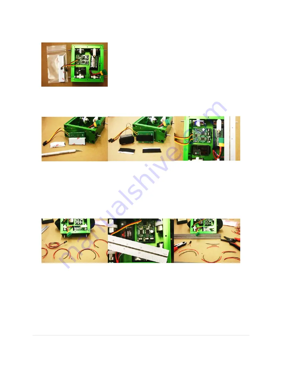
Arrange your battery, receiver, and speed controller on the bottom plate, as you expect to place them in
the finished robot.
The battery is in there just to make sure sufficient room is being
left for it.
Make sure there is sufficient clearance between everything and
the motors, allowing for spacing up of the receiver and speed
control when they are attached using the included Velcro.
Mark the location of your receiver and speed controller on the
bottom plate.
3.3
S
TEP
4
–
A
TTACH
E
LECTRONICS
:
Attach your receiver and speed controller using the Velcro.
Make good use of the Velcro by making sure that parts are mounted firmly enough (as
shown).
3.4
S
TEP
5
–
W
IRING
P
REPARATION
:
Determine wire lengths needed to connect your motors to your speed control and from the battery to
the switch and speed control:
Measure from the motor solder lugs to the speed control lugs.
Place the battery in the chassis, and determine wire lengths needed to connect to the power
switch. The negative will go from the battery to the negative contact on the board and the
positive will do the same but will be interrupted by the switch.
Trim the wires to size and strip the ends allowing a 5mm contact on each end.
For easier assembly, tin the wires after they have been cut and striped to length.
At the same time, trim the power LED leads to an appropriate length to connect to the power
lugs on the speed control, and tin if desired.