background image

32

Section 5 - Water & Waste System

320 Outrage-Owner’s Manual

FULL

FULL

OVERBOARD

DISCHARGE

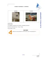
Tank level light

25A Breaker
(for overboard
discharge)

Key
switch

ENVIRONMENTAL CONSIDERATIONS:
The Environmental Protection Agency (EPA) stan-
dards state that in freshwater lakes, reservoirs, im-
poundments whose inlets or outlets are such as to
prevent the ingress or egress by vessel traffic subject
to this regulation, or in rivers not capable of naviga-
tion by interstate traffic subject to this regulation.
Marine sanitation certified by the United States Coast
Guard (U.S.C.G.) installed on vessels shall be de-
signed and operated to prevent the  overboard dis-
charge of sewage, treated or untreated or any other
waste derived from sewage.  The EPA standards fur-
ther state that this shall not be construed to prohibit
the carriage of Coast Guard certified flow through
treatment devices which have been secured so as to
prevent such discharges. They also state that the
waters where a Coast Guard certified marine sanita-
tion device permitting discharge is allowed include:
Coastal waters, Estuaries, The Great Lakes and In-
tercoastal waterways, Freshwater lakes and Impound-
ments accessible through locks and other flowing wa-
ters that are navigable interstate by  vessels subject
to this regulation. (40CFR 140.3)

Standard Waste Panel

Optional Waste Panel

Tank level light

MACERATOR
The 320 Outrage waste system also incorporates the
use of a  macerator. The macerator pump draws solid
and liquid waste from the holding tank of the unit
and processes it prior to discharging it overboard
through a lockable seacock. The pump is designed
to handle waste, toilet tissue and facial tissue and
will not pump solid objects. 

There are bodies of

water where discharge of raw sewage is prohib-
ited. Keep seacock lock engaged when in waters
where discharge is not permitted. 

 The dockside

facility will have a connection to fit your boat.  It is
important that you close your macerator discharge
seacock on the 320 Outrage prior to using the

Push button/Switch
(for vacuum pump)

MACERATOR OPERATION:
The macerator key switch panel is located on the
lower section of the electrical panel. The key switch
controls the macerator pump. The overboard dis-
charge seacock must be in the OPEN position prior
to operation. The key must be turned and held for
the macerator to operate properly.
MAINTENANCE:
After long periods of non-use, the macerator pump
may not turn freely.  Regular use of the system will
reduce the chances of this occuring. If the system
does require maintenance contact your nearest dealer
for more information. Because your waste system is
a low water use device, there is special paper that
must be used to prevent clogs. The manufacturer has
provided information regarding the type of paper that
must be used. NEVER use residential tissue paper
in your marine waste system.

Push button/
Switch
(for vacuum
pump)

shoreside discharge function.
Contact your dealer or Coast Guard station for infor-
mation on overboard discharge and its penalties.

Summary of Contents for 320 Outrage

Page 1: ...S THE RIGHT TO MAKE CHANGES AT ANY TIME WITHOUT NOTICE IN THE COLORS EQUIPMENT SPECIFICATIONS MATERIALS AND PRICES OFALL MODELS OR TO DISCONTINUE MODELS SHOULD CHANGES OR MODIFICATIONS TO THE MODELS BE MADE BOSTON WHALER IS NOT OBLIGATED TO MAKE SIMILAR CHANGES OR MODIFICATIONS TO MODELS SOLD PRIOR TO THE DATE OF SUCH CHANGES THE FOLLOWING ARE REGISTERED TRADEMARKS OF THE BRUNSWICK CORPORATION 180...

Page 2: ... consistently choose Boston Whaler because of their seaworthiness dependablility and the inherent safety of a hull that won t sink even if severely damaged Boston Whalers are built to last For over 40 years Boston Whaler has strived to make each model better providing you with a safe and fun boating experience That is the reason we offer a 10 year limited transferable warranty It is also an excell...

Page 3: ... Freshwater Pump 28 Freshwater Shower 28 Maintenance 29 Disinfecting the System 29 Winterizing the System 29 Raw Water 30 Operation Maintenance 30 Raw Water System Diagram 30 Seacock Operation 30 1 Head System 31 Dock Side Discharge 31 Standard Waste System Diagram 31 Optional Inland Waters Diagram 31 Macerator 32 Operation Maintenance 32 Environmental Considerations 32 Section 6 Bilge System Bilg...

Page 4: ...e engine serial numbers and part numbers when writing about or ordering parts for your engine Our Hull Boston Whaler hulls are constructed with our pat ented Unibond construction This involves shoot ing high density foam into a closed mold system The foam expands to fill voids in the hull and when the finished product is pulled from the mold the deck and the hull are chemically bonded to form a so...

Page 5: ...orsepower 600 HP 447 kw Minimum Horsepower 400 HP 298 kw Fuel Capacity 300 Gal U S 1135 L Water Capacity 40 Gal U S 151 L Waste Capacity 6 5 Gal U S 24 L Waterline Specifications Dimensions Specified measurements are approximations and are subject to variance NOTICE NOTICE Optional equipment and loading of the boat will af fect the draft measurements Follow the recommen dations listed on your capa...

Page 6: ... Lockable 19 Instrument Panel 20 Stainless Steel Steering Wheel w Knob 21 Gear Shift Throttle Control 22 Molded Console Footrests 23 Electronics Box Mounting Surface 24 Console Door Lockable 25 Portlight w Screen 26 Console Cupholders 2 27 Port Fuel Fill 28 Stainless Steel Spring Cleat P S 29 Gunwale Mounted Rodholders 2 P S 30 Port Fishbox Insulated 31 Stainless Steel Hawse Pipe w cupholders 2 P ...

Page 7: ...ush Toilet 10 Vertical Rodholder 11 Freshwater Sprayer and Sink 12 Downrigger Weight Holder 13 Transom Shower 14 Hardtop Fiberglass 15 Lifejacket Storage 16 Electronics Box 17 Hardtop Courtesy Lights 18 Map Light RED 19 Spreader Lights 20 Hardtop Hatch 21 Stainless Steel Toe Rails Port Starboard 22 Electric Trim Tabs 23 Windlass Anchor 1 2 3 4 5 6 7 8 9 10 11 12 13 14 15 16 21 22 17 19 18 20 23 24...

Page 8: ...phics Fighting Lady Yellow w Black Graphics Light Blue w Black Graphics Wasabi w Black Graphics 2 Red or Blue Graphics Striping Logos 3 Tall Bow Rail 4 Radial Outriggers for Hard Top P S 5 225 CXXL Optimax DTS Dual Engines 6 275 CXXL DTS Verado 4 Stroke Dual Engines 7 12V Receptacle port starboard gunwales aft 8 Butane Stove Portable 9 Bow Tow Eye 7 ...

Page 9: ...26 13 Storage 1 2 3 4 5 7 8 9 10 11 6 14 16 108 Gal 409L Forward Insulated Fishbox 17 80 5 Gal 305L Forward Locker Starboard 18 Forward In Deck locker 19 Console Lockable 20 Console Cupholder 2 21 Swim Ladder Stowage 22 Motorwell Access Oil Tank Storage 23 Port Fishbox 80 Gal 302L Starboard is same 24 Console Electronics Box Lockable 25 Forward Cupholder Starboard is Identical 26 80 5 Gal 305L For...

Page 10: ...dripping It is recommended that the underwater fittings be re moved cleaned and resealed every other year NOTICE If the through hull fittings need to be replaced it is recommended that an authorized Boston Whaler dealer perform this type of repair Through hull fit tings that are improperly installed can cause pre mature hull failure and may void the Boston Whaler limited warranty NOTICE 16 Livewel...

Page 11: ...p erate the engine while loading or unloading swimmers divers from the swim platform ladder Be aware of your footing while the boat is underway slipping or falling could result in serious injury or death especially if the boat is in motion or in rough water Keep the accommodation deck clean so if movement is neccessary it will be free of obstruction Gelcoat surfaces are slippery when wet Use ex tr...

Page 12: ...assengers on the deck should be limited to decrease the chances of slipping or falling while underway DANGER 1 2 3 Standard Seating Arrangement 1 Helm Companion seats with snap on cushions adjustable port seat 2 Forward Console Seat 3 Forward Seating 4 Stern fold away seat 4 320 Outrage Canvas Arrangement 1 Bait Prep Station Cover Black 2 Console Cover Black 3 Weather Curtain Visor Black or White ...

Page 13: ...e Label Locations NOTICE WARNING CO HELM WARNING CO HELM 1811368 1811368 DANGER CO TRANSOM DANGER CO TRANSOM 1811367 1811367 1743511 1743511 1744740 1744740 1744745 1744745 1752856 1752856 1743504 1743504 1754632 1754632 1745514 1745514 1746896 1746896 1774308 1774308 1400LB 635KG 1400LB 635KG 1799311 1799311 LABEL CAUTION OIL TANK LEVEL LABEL CAUTION OIL TANK LEVEL 1795087 1795087 LABEL PROP 65 H...

Page 14: ...der Port tank 7 Engine fuel supply 8 Ground wire Port tank 9 Fuel pick up 10 Port fuel selector valve 11 Starboard fuel selector valve The starboard fuel tank is similar in assembly and is not shown in its entirety 4 2 3 1 5 6 7 8 9 10 11 Fuel System CAUTION Leaking fuel is a fire and explosion hazard inspect the system regularly Examine fuel tanks and exposed lines for leaks and corrosion DANGER ...

Page 15: ... port and starboard sides of the motorwell hatch The primer bulbs are used to draw fuel from the tank to the engine usually after the fuel has been drained from the entire system There are also in structions regarding proper use of the primer bulb in the engine manufacturers handbook From fuel tank Port Tank Starboard Tank To Port Engine To Starboard Engine Port Tank Selector Valve Starboard Tank ...

Page 16: ...ssionally cleaned If you are frequently changing fuel filter water separators and notice a loss in power consult a professional tank cleaning contractor regarding this procedure and proper disposal of residue and water Remote Oil Tank Location sterndeck has been removed Optional engine oil supply 2 3 Gal 11 3L The 320 Outrage may be equipped with a remote oil system This system consists of two 3 G...

Page 17: ...afe conditions such as suspended on a sling or in a situation that in creases the likelihood of static discharge NEVER use homemade containers to fill your fuel tanks Fuel carried on board outside of a fixed fuel sys tem should be stored in an approved container or in a portable tank such as provided for outboard engines and be stowed safely outside of the engine or living compartment s Shut down ...

Page 18: ... Box Release Strap Tie down strap Never reset a breaker without first determining and correcting the cause of the trip Should a circuit re peatedly trip have a qualified electrician determine and correct the cause Never use an open flame in the battery storage area Avoid striking sparks near the battery A battery will explode if a flame or spark ignites the free hydrogen given off during charging ...

Page 19: ...heswitch on the left is for the port battery and engine the right switch is for the starboard battery and engine Dual Battery Switches Selector Knob Battery 1 Selection Battery 2 Selection Batteries OFF Selection Batteries ALL Selection Dual Engine Battery Switch Configuration Both batteries un connected preferred position when boat is not in use STARBOARD ENGINE ALL 2 1 O F F Normal position whil...

Page 20: ...icians Boston Whaler does not recommend that you attempt to work on the electrical system yourself instead we suggest that you take it to an authorized Boston Whaler dealer for electrical service Boston Whaler reserves the right to change or up date the electrical system on any model at any time without notice to the consumer and is not obligated to make any updates to units built prior to the cha...

Page 21: ...Section 4 Electrical System 320 Outrage Owner s Manual 19 Main Breaker Panel Diagram Hull Wiring Diagram ...

Page 22: ...n 4 Electrical System 20 320 Outrage Owner s Manual Active Deck Suspension System ADSS Wiring Diagram Anchor Windlass Wiring Diagram Waste System Overboard Discharge Diagram Waste System Inland Waters Diagram ...

Page 23: ... 20 21 12 16 17 14 15 13 320 Outrage Instrument Panel Arrangement SELECT HOME RPM AIR F NAV FUEL FAVORITES PROPULSION PM 78 3 08 H20 0 0 0 N VESSEL SYSTEM SETTINGS PSI RPM H20 0 0 0 PSI PORT STBD START STOP START STOP 12V HORN NAV ANCH COURTESY LIGHT INTERIOR AFT BILGE FWD BILGE SPREADER LIGHTS RAW WATER LIVEWELL PUMP LIVEWELL LIGHT ACC 1 ACC 2 FRESH WATER FWD FISH PUMP STBD FISH PUMP PORT FISH PU...

Page 24: ...r 9 Favorites Directory 10 Navigation Fuel Directory 11 Propulsion Directory 12 Settings Directory 13 Vessel Directory 14 System Directory Note To get the most out of your System View you must read the manual provided by the manufacturer The manual will give you information to properly operate the various features of the system 1 2 3 4 5 6 8 7 9 10 11 12 13 14 Section 4 Electrical System 320 Outra...

Page 25: ...gnition Shut down Switch Clip attaches to you The decision to use the safety switch is up to you the owner operator NOTICE Electric Downrigger Receptacles Optional The location for mounting of the downrigger base is important refer to the wood location diagram for ar eas on the gunwales that are specifically designed for withstanding the stress generated by a downrigger There are a variety of down...

Page 26: ...rim Tabs Switch 1d 5 Amp Breaker for Stereo 1e 10 Amp Breaker for Helm 12V Receptacle 2a 10 Amp Breaker for Interior 12V Receptacle 2b 10 Amp Breaker for Courtesy Interior Lights 2c 20 Amp Breaker for Port Fishbox Pump 2d 20 Amp Breaker for Stbd Fishbox Pump 2e 20 Amp Breaker for Fwd Fishbox Pump 3a 15 Amp Breaker for Water Pump 3b 15 Amp Breaker for Raw Water Pump 3c 6 Amp Breaker for Livewell Pu...

Page 27: ...d to the right of the ignition switch marked Start Pressing these switches will start the engine the switch has been designated for Shutting down the engines requires just pushing lower portion of the Port Ignition Starboard Ignition switches forward Engine Starting Procedure The gear shift throttle control will not allow engine start ing if the control levers are in any other position than NEUTRA...

Page 28: ...o en sure that the navigation lights are in good working order and that the proper lighting is shown Navigation Lighting NOTICE 112 Port navigation light red 112 Starboard navigation light green 360 all round light white Off Navigation Lights Anchor Lights Navigation light Anchor light switch The more lights a vessel has the larger it is and the more important it is for you to avoid it HORN NAV AN...

Page 29: ...rse polar ity before switching the shore power main battery charger switch to the ON position The battery charger is energized and will charge the batteries automatically when the shore power main battery charger switch is activated Male plug end Female plug end Shore power cord 50 ft 15 2M BATTERY CHARGER With the battery charger you will have the ability to charge your batteries without engines ...

Page 30: ...reach the freshwater pump through a removable access hatch located on the lower aft wall of the con sole interior FRESHWATER SHOWER There are freshwater showers located on the starboard end of the cockpit transom wall and the forward sec tion of the console The cockpit sprayer has an en closure that the shower head and hose fits into The shower hose extends about 6 ft 1 82m Once the system has bee...

Page 31: ... entire system Flush the entire system thoroughly several more times with potable water Now the system is ready for use fill with pot able water Ask your dealer if this has been done and what pro cedures are needed to accomplish this This should be done annually or before using the system if it has been laid up for an extended amount of time WINTERIZING THE SYSTEM If the water system will not be u...

Page 32: ...n The seacock can be ac cessed through the lower aft wall inside the console The RAW WATER switch on the instrument panel controls pump operation MAINTENANCE Maintenance of the raw water system will require you to check the fittings and hoses for system integ rity to prevent leaks The system should be run at least every other month to keep the pumps impellers in good condition The Livewell and raw...

Page 33: ...n to fit your boat Shore side discharge is a preferred method of waste disposal VacuFlush Toilet Waste System Diagram 1 VacuFlush Toilet 2 Waste Discharge Hose to Holding Tank 3 Freshwater Supply Line from Tank 4 Vent from Holding Tank 5 VacuFlush Holding Tank 6 Macerator 7 Shoreside Discharge Hose Deck Fitting 8 Discharge Line from Macerator 9 Lockable Discharge Seacock 1 2 3 5 8 7 4 Your 320 Out...

Page 34: ...rates the use of a macerator The macerator pump draws solid and liquid waste from the holding tank of the unit and processes it prior to discharging it overboard through a lockable seacock The pump is designed to handle waste toilet tissue and facial tissue and will not pump solid objects There are bodies of water where discharge of raw sewage is prohib ited Keep seacock lock engaged when in water...

Page 35: ...FT BILGE and FWD BILGE on the switch panel Depressing the switch will energize the pump regardless of the position of the float switch Each pump discharges water over board via a thru hull fitting MAINTENANCE The bilge pump is a completely sealed unit and main tenance is very simple but it will require you to check around the float switch for debris and gummy bilge oil that could impede the bilge ...

Page 36: ... livewell they can be used to adjust the level of water in the livewell 1 Livewell 45 gal 170 3L 2 Livewell Bucket Upper Overflow 3 Livewell Bucket Lower Overflow 4 Livewell Light 5 Livewell Fill 6 1 5 inch Y Coupling 7 1 5 inch T Coupling 8 Flow Control Valve 9 12V 1100 GPH Raw Water Pump 10 Raw Water Pump Seacock 11 Sink Drain Hose 12 1 inch to 1 5 inch T Coupling 13 To Drain Fitting on Transom ...

Page 37: ...recreational water activities Special care and attention must be taken to ensure proper performance of the steering system and should include the following After the first few hours of operation and at regular intervals check all fasteners and the com plete steering system for security and integrity Check all moving parts to be sure they are free of salt build up and other foriegn material Inspect...

Page 38: ...ree aside from regular fluid checks and visually inspecting the out side of the unit for signs of leaks or damage Remove the shroud and unscrew the cap to check the fluid level in the reservoir There is a filter insert that needs to be checked and cleared if necessary Fill as necessary Make it a habit of checking the fluid level before each trip Use ONLY SAE 0W 30 Full Synthetic Power Steer ing Fl...

Page 39: ...m and will allow you to operate the throttle without engaging the propeller This button will au tomatically engage the shifting mechanism once the throttle control has been moved back to its center position you will hear and feel a click when it is engaged Moving the lever forward engages the for ward gear and then the throttle advance To reverse power bring the control lever back to engage the re...

Page 40: ...ation Power Trim Switch This view represents the DTS for a dual engine set up The single engine DTS set up has a single portside arm Port Starboard engine trim switches The helm seats on the 320 Outrage are independently adjustable for your comfort There is a handle on the front of the seat track that when pulled will allow the seats to be pulled forward there are hole stops in the track that will...

Page 41: ...eral changing to a lower pitch propeller will increase acceleration and load pulling capability with a slight decrease in top end speed If you choose to change propellers the type should be discussed with your Boston Whaler dealer PROPELLER All propellers are designed to provide maximum for ward thrust so the reverse thrust of the propeller will not be as efficient The 320 Outrage uses propellers ...

Page 42: ... on the center part of your console above the throttle control Short momentary bursts of the rockers will achieve proper attitude of the hull The trim tab switch is marked bow up and bow down Using the trim tabs will Level the boat fore and aft Reduce resistance in the steering system Give you a smoother more stable ride Speed will increase and there will be less strain on the engines MAINTENANCE ...

Page 43: ...ifting sling labels port starboard The 320 Outrage has 6 10 inch cleats two located at the bow two located amidship and two located at the stern on the gunwale walls be tween the under gunwale rodholders The cleat is used to secure the boat to the dock While loading unloading or mooring please learn the proper way to secure the boat and how best to use the moor ing points of your boat The bow eye ...

Page 44: ...lso contributed to the forma tion of blisters on the hull There are a variety of ways to prevent the formation of hull blistering Ep oxy coatings can be applied to the hull followed by hull painting An alkyd urethane silecone marine paint can also be used to aid in the prevention of hull blisters Reducing the amount of time that your boat stays in the water also helps prevent hull blisters from fo...

Page 45: ...ter and water temperature can all affect the types of growth that you will find on your boats hull Long Term Storage Never start or run your outboard even momentarily without having water circulating through the cooling water intake holes in the gear case This will prevent damage to the water pump running dry or overheat ing of the engine NOTICE Store the batteries in a cool dry location Keep the ...

Page 46: ... the cable ends DRAINAGE It is important to raise the bow of the boat enough to allow for proper drainage of water from the deck and bilge area Make sure all the drainage fittings are clear and free of debris Store the engine in an upright position to promote adequate drainage of water NEVER trailer the boat with the sun top in the open position Damage to the frame canvas and securing straps can o...

Page 47: ...he coupler and the hitch ball are properly seated and locked Maintain your trailers lighting braking and safety restraint systems as required Refer to the engine owner s manual for proper engine support while trailering DANGER Tie down straps should never be used by themselves they are only used to help in keeping the boat secured to the trailer Make certain that the safety chain is prop erly secu...

Page 48: ...turer before using the an chor windlass Follow all recommendations and in structions regarding its proper use and care ANCHOR Lowering the Anchor Be sure that there is enough rope for the depth of water you will be anchoring in and secure rode to both the anchor and the boat Stop completely before lowering the anchor Keep feet clear of coiled line as it pays out Turn the anchor light on at night o...

Page 49: ...he center socket and turning it counter clockwise will loosen the anchor windlass chainwheel Turn the handle counterclockwise will allow you to lower your anchor while turning it clockwise will raise it The anchor windlass is located in the anchor locker The anchor windlass gives you a mechanical means of raising and lowering the anchor OPERATION The anchor windlass is controlled by a switch lo ca...

Page 50: ...Section 11 Maintenance Log Notes Engine Hours Serviced by Maintenance Performed After the scheduled services are performed fill out the areas below Date Maintenance Record Notes 320 Outrage Owner s Manual ...

Page 51: ...Section 12 ADSS 320 Outrage Owner s Manual ACTIVE DECK SUSPENSION SYSTEM OPERATION MANUAL ...

Page 52: ...r separator located portside in the forward console C TheADSS instrument panel located on the dash The system is powered by the on board batteries and protected by two thirty 30 amp breakers located on the main breaker panel labeled ADSS The system only lessens the impact loading to those occupants who are STANDING ON THE SUSPEN SION DECK Occupants outside the suspension deck will be subjected to ...

Page 53: ...per half of the LIFTING JACKS switch for 10 seconds Once the jacks are raised the system can be powered down by pressing the bottom of the power switch Operation If there is a pneumatic failure during operation the suspension deck will lower and not return If this should occur raise the lifting jacks so the deck returns to normal operating height and then power down the system The suspension deck ...

Reviews: