background image

5

Control Functions (cont.)

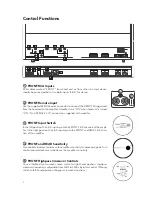
“Q” Control

“Q” Control is active when the highpass crossover is engaged and is centered
on the selected crossover point. The range of operation is 0.7–1.2.

REAR RCA Inputs

RCA cables marked “REAR” from head unit or other line level device should be
connected here. Use both inputs (L & R) for stereo.

REAR Remote Input

This remote input is parallel to the FRONT remote input and does not need to
be connected for the amplifier to operate. Use either remote input to turn the
amplifier on. Do not connect 12V accessories to this input.

REAR Input Switch

In the left position, the L & R inputs go to the REAR L & R channels of the ampli-
fier. In the right (MONO) position, the inputs are summed. Use this setting when
the REAR channels are used with a subwoofer.

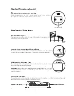
Lowpass Slope and Crossover Controls

Select appropriate crossover slope of 12 or 24dB/octave by
moving LOWPASS SLOPE switch. Lowpass crossover fre-
quencies are adjustable from 50Hz to 350Hz by rotary control.
Move filter switch to “ON” position to engage.

Status LED Indicators

GREEN indicates the normal operating condition; the amplifier is “ON.” GREEN
and RED together are normal when the amplifier is first turned “ON”; RED will
turn off after a few seconds. When both GREEN and RED remain on, the ampli-
fier is in thermal shutdown condition. RED only indicates a fault condition, “SAFE.”

7

8

6

7

8

10

11

9

(tuned crossover frequency)

0dB

+1.6dB

-3dB

t

1.2

.95

.707

dB

Q

L OW PA S S   S L O P E

1 2 d B 2 4 d B

M O N O

1 2 d B

S T

L OW PA S S

O F F

O N

5 0

3 5 0

H z

2 0 0

Summary of Contents for GT-42

Page 1: ...GT 42 4 Channel High Current High Power Amplifier ...

Page 2: ...Power B and power ground connection 11 Remote input connection 11 Speaker output connection 11 Installation fuses and wiring cont 12 Mono subwoofer operation 12 Setup Tuning Full Range Speakers 12 Music 12 Front and rear sensitivity controls 12 Front and rear crossover controls 12 Setup tuning full range speakers cont 13 Head unit 13 Volume 13 Front input sensitivity control 13 Front crossover con...

Page 3: ...se 3dB 10Hz 95kHz Signal to Noise Ratio A Weighted 100dB Dimensions 21 4x215 8x87 8 57 x 548 x 225mm GT 42 Features 4 Channel High Current Amplifier 2Ω Bridge Stable Mono Operation Power Increase with Input Voltage Rise Advanced Cooling Allows Varied Mounting Positions Adjustable Feet for Varied Mounting Surfaces Security Cover Protects Control Settings 24dB or 12dB Octave Lowpass Setting Continuo...

Page 4: ...nals Turn control counterclockwise to decrease the amplifier sensitivity FRONT Highpass Crossover Controls To use 12dB octave crossover move switch to right hand position Highpass crossover frequency is adjustable from 20Hz to 350Hz by rotary control Moving switch to left hand position will bypass crossover functions 1 2 1 2 3 4 5 12 6 14 4VDC B B GROUND GND GND L R MONO FRONT SPEAKER OUTPUT MONO ...

Page 5: ...li fier In the right MONO position the inputs are summed Use this setting when the REAR channels are used with a subwoofer Lowpass Slope and Crossover Controls Select appropriate crossover slope of 12 or 24dB octave by moving LOWPASS SLOPE switch Lowpass crossover fre quencies are adjustable from 50Hz to 350Hz by rotary control Move filter switch to ON position to engage Status LED Indicators GREE...

Page 6: ...ar installation obstructions on the mounting surface WARNING Before driving the mounting screws through any surface be sure of what is behind that surface Check for the gas tank brake lines and any vehi cle wiring harness Vents Side and Rear The cooling vents must be kept clear of obstructions once the amplifier is installed Failure to do this could lead to premature thermal shutdown or amplifier ...

Page 7: ...together without additional hardware Wire Connection Amplifier accepts stripped wire directly into the terminal blocks Speaker outputs accept 8 gauge and the DC power and ground accept 4 gauge Tighten with supplied hex wrenches Fuses Amplifier accepts standard AT style automotive blade fuses FUSE 3 x 20A GT 42 GT 20 ...

Page 8: ...tion correctly the electrical system of the vehicle should be professional ly checked for overall electrical capacity When used the amplifier will increase the demand on the battery and alternator Therefore both should be thoroughly evaluated before installing the amplifier to ensure they are in normal operating condition and able to handle the increased demand the amplifier will present to the ve...

Page 9: ... an amplifier in the engine compartment of a vehicle WARNING Before driving the mounting screws through any surface be sure of what is behind that sur face Check for gas tank brake lines and any vehicle wiring harness Installation Amplifier Mounting GT 42 12 6 14 4VDC B B GROUND GND GND L R MONO FRONT SPEAKER OUTPUT MONO REAR SPEAKER OUTPUT L R ON SAFE STATUS 57mm 21 4 ...

Page 10: ... wedging into position Amplifier should be mounted using the movable mounting feet and the provided mounting screws Installation Fuses and Wiring Installation Amplifier Mounting cont Amplifier Fuses Although the amplifier has internal fuses additional fusing should be pro vided at the battery on the positive power wire going to the amplifier An inline fuse should be installed at no more than 18 46...

Page 11: ...nection Use the supplied FEMALE slide connector to connect the REMOTE trig ger lead from the head unit to the amplifier Crimp connector to wire from head unit that controls remote turn on refer to head unit owner s manu al Once the slide connector is crimped into place carefully push connector onto recessed male REMOTE terminal adjacent to the RCA Input pair Only one 1 remote turn on terminal shou...

Page 12: ... both of these characteristics and should be used 2 FRONT and REAR Sensitivity Controls Turn controls all the way counterclockwise minimum position In this position the amplifier will be less sensitive to the input signal from the head unit Setup Tuning Full Range Speakers FRONT crossover control REAR crossover control 3 FRONT and REAR Crossover Controls Crossovers should be turned off during this...

Page 13: ...ontrol fully counterclockwise Move crossover switch to the right ON position Slowly rotate FRONT input sensitivity control clockwise until maximum undis torted playing level is heard from the speakers Listen closely for bottoming from the speakers If detected rotate FRONT input sensitivity control coun terclockwise until it is eliminated Slowly rotate FRONT highpass crossover con trol counterclock...

Page 14: ... Controls Setting levels for the rear channels proceeds the same as for the front except for the elimination of the Q control settings Crossover selector switch must be set to HP and filter switch must be set to ON If the loudspeaker being used is capa ble of full range operation filter should be set to OFF Setup Tuning Rear Fill Speakers You may set the rear channels for summed mono operation fro...

Page 15: ...se Swap positive and negative connections at the speaker outputs where the subwoofer is connected to the amplifier It is beneficial to listen to the subwoofer connected in both phase conditions The subwoofer should be left in the condition in which the strongest bass response is noted Setup Tuning Subwoofers cont 3 Head Unit The head unit should have all controls such as bass treble balance and fa...

Page 16: ...ith Full Range Rear 6 5LF 6 5LF 6 5LF 6 5LF fuse to battery terminal to ground fuse to battery terminal to ground System B Full Range Front with Rear Fill 6 5LF 6 5LF 6 5LF 6 5LF fuse to battery terminal to ground fuse to battery terminal to ground ...

Page 17: ...e Subwoofer 2Ω System D Main Speakers with Parallel 4Ω Subwoofers 2Ω load 6 5LF 6 5LF 10 5LF 2Ω fuse to battery terminal to ground fuse to battery terminal to ground 6 5LF 6 5LF 6 5LF 6 5LF fuse to battery terminal to ground fuse to battery terminal to ground ...

Page 18: ...pment cables leading to amplifier Verify RCA cables are of good quality with no breakage to internal shields RCA cables from source to amplifier are not run alongside power Amplifier Output Distorted Music not Recorded with Intentional Distortion Verify Source output to amplifier is not distorted Amplifier input sensitivity is correctly adjusted Amplifier Shuts Down Red and Green LEDs are Lit Ampl...

Page 19: ...ities are to use the system according to the instructions supplied to provide safe and secure transportation to an authorized Boston Acoustics service representative and to present proof of purchase in the form of your sales slip when requesting service Excluded from this warranty is damage that results from abuse misuse accidents shipping or repairs or modifications by anyone other than an author...

Reviews: