-6-
EYE PROTECTION which conforms to ANSI specifications and provides protec-
tion against flying particles both from the FRONT and SIDE should ALWAYS be
worn by the operator and others in the work area when loading, operating or ser-
vicing this tool. Eye protection is required to guard against flying fasteners and
debris, which could cause severe eye injury.
The employer and/or user must ensure that proper eye protection is worn. Eye
protection equipment must conform to the requirements of the American National
Standards Institute, ANSI Z87.1-1989 and provide both frontal and side protection.
NOTE: Non-side shielded spectacles and face shields alone do not provide ade-
quate protection.
TO PREVENT ACCIDENTAL INJURIES:
• Never place a hand or any other part of the body in nail discharge area of tool
while the air supply is connected.
• Never point the tool at anyone else.
• Never engage in horseplay.
• Never pull the trigger unless nose is directed at the work.
• Always handle the tool with care.
• Do not pull the trigger or depress the trip mechanism while loading the tool.
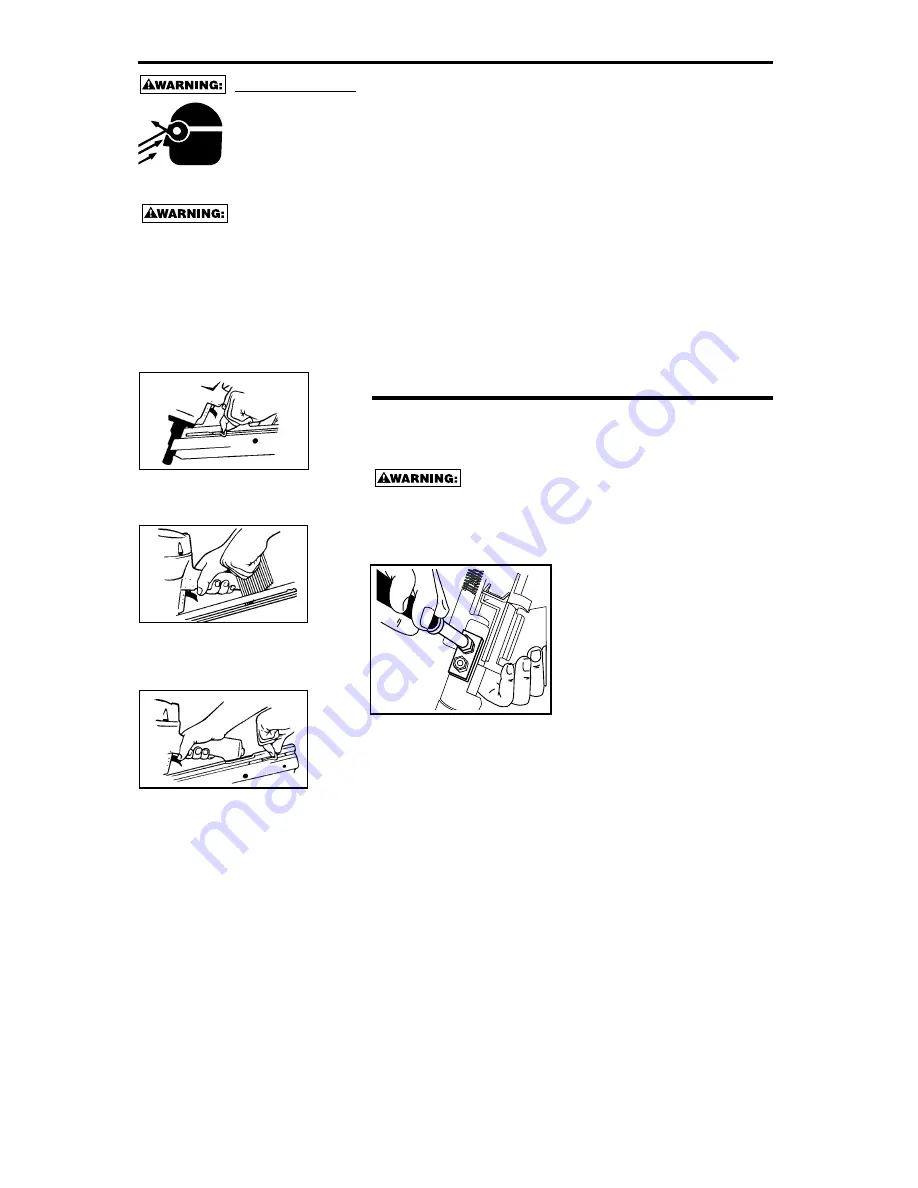
LOADING THE N95RHN
1. Open the magazine:
Pull pusher back to
engage latch.
2. Load Nails:
Hold nailer down with maga-
zine tilted downward. Insert
sticks of nails
3. Close Magazine:
Release latch by pulling latch tab
and pusher together slightly to
disengage, slide pusher against
nails.
NOTE: Use only All-Specs™ nails rec-
ommended for use in Bostitch N95RHN
series nailers or nails which meet the
Bostitch specifications.
FASTENER DEPTH CONTROL ADJUSTMENT
The Fastener Depth Control Adjustment feature provides control of the nail
drive depth from flush with or just above the work surface to shallow or deep
countersink.
TO ADJUST THE FASTENER DEPTH
CONTROL:
DISCONNECT TOOL FROM AIR SUPPLY BEFORE ATTEMPTING ANY
PARTS DISASSEMBLY AND BEFORE CHANGING THE WORK CON-
TACTING ELEMENT ADJUSTMENT.
1. With air pressure set, drive a few
fasteners into a representative
material sample to determine if
adjustment is necessary.
2. If adjustment is required, disconnect
air supply.
3. If adjustment to the drive depth is
required, measure the difference in
depth between the nail as driven in
the sample material and the desired
drive. The depth control should be
changed by the same amount. To
reduce the drive depth, the work
contacting element should be lengthened. To obtain a deeper drive, the
work contacting element should be shortened.
4. Note the level at which the depth control is assembled. Decide what
adjustment is required to achieve the length change determined in (2)
above. The dashes on the front of the depth control are evenly spaced
.08” (2mm). Zero would have the deepest countersink and 12 may leave
the nail head above the work. The tool is shipped from the factory on
setting “0”.
5. To make the adjustment, use a 10mm wrench or nut driver to loosen the
(2) elastic stop nuts on the depth control approximately 2 full revolutions.
It is not necessary to remove these nuts. Move the lower portion of the
depth control to the desired height and tighten the nuts. Do not
overtighten. Check that the work contacting element operates freely
without sticking or binding.
6. Reconnect air supply and drive a few fasteners in a sample of material to
determine if adjustment is correct. If further adjustment is necessary,
disconnect air and repeat above.


