Snowplow Assembly Procedure
7
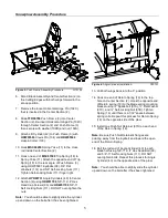
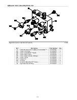
Figure 7.
Assembly of Hydraulic Connections.
G10013
24. Attach one end of Hydraulic Hose (49) to the
lower port of Lift Cylinder (42).
Attach the
opposite end of Hydraulic Hose (49) to the center
Hydraulic Fitting (54). Tighten connection
securely.
25. Apply thread sealant compound (do not use
Teflon Tape) to the threads of the 3/8” MNPT end
of
HYD07042
Hydraulic Hose (52). Thread the
hose into the port on Angle Cylinder (40) and
tighten securely.
Note:
Do not apply thread compound to the ¼” end of
the hose.
Note:
Do not get thread compound on the end of the
hose since the compound will contaminate the
hydraulic system.
26. Attach the loose end of
HYD07042
Hydraulic
Angle Hose (52) to the corresponding fitting on
the hydraulic manifold. Tighten all hydraulic
connections securely.
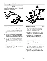
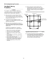
Figure 8.
Light Bar Assembly. (Standard)
G10132
27. Attach Light Bar (13) to the top of Coupler
Assembly (1) using two Hex Head Cap Screws
(91) and Hex Head Self Locking Nuts (109).
Note:
The light bar should be positioned as close to
the Coupler Tower as possible. Only two holes will be
aligned for normal installations. Only two bolts per side
are needed to secure the light bar.
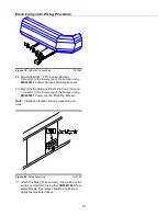
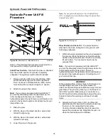
Figure 9.
Light Bar Assembly Adjustment.
G10131
Note:
Figure 9 illustrates that the Coupler Assembly
and Light Bar have two sets of 1 inch adjustment holes
for mounting on different vehicles. These adjustment
holes may be needed in order to move the light bar
away from the vehicle’s hood.


