9
DR-3
fig.volume
3.
Use an oscilloscope to observe the waveforms from OUTPUT L/R (PIN
jack) on the DR-3.
fig.lineout-1
• Waveforms like those shown above must be output from LINE OUT L/
R.
• They must be rectangular waves phase-shifted by 90 degrees.
• The waveform height must be from 1.8 V to 2.4 V.
4.
Observe the waveform from the tip of R (MONO) on the DR-3.
Nothing must be plugged into L (PHONE) at this time.
fig.lineout-2
• A stepped waveform like the one shown above must be output from R
(MONO).
5.
Observe the waveforms from the tip of L (PHONE) and from the tip of R
(MONO) on the DR-3.
fig.lineout-3
• They must be rectangular waves phase-shifted by 90 degrees, like those
shown above.
• The waveform height must be from 1.8 V to 2.4 V.
6.
Disconnect the plug from R (MONO).
Insert a stereo plug into L (PHONE) and waveforms of the tip and the
ring.
fig.lineout-4
7.
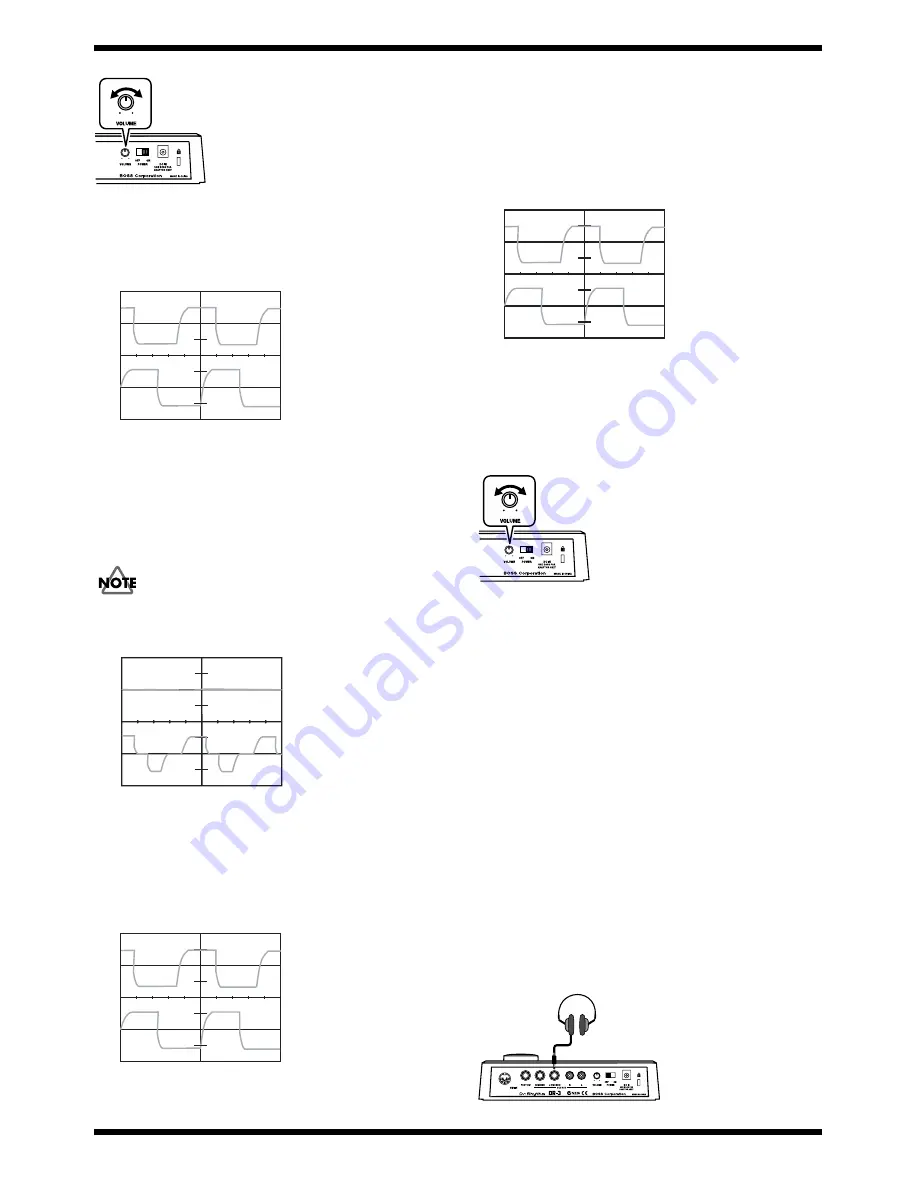
Turn [VOLUME] on the DR-3 to “MAX,” then to “MIN,” then back to
“MAX,” and make sure the waveforms change smoothly.
Also, make sure that the waveforms disappear completely when
[VOLUME] is set to “MIN.”
fig.volume
8.
Press the [EXIT] button to end the SQUARE Check.
13.SINE Check
This item is used only during the shipping test at the factory.
You need not use it when servicing in the field.
14.MUTE Check
This item is used only during the shipping test at the factory.
You need not use it when servicing in the field.
15.Ending the Test Mode
Switch off the DR-3.
16.Checks for Normal Operation
1.
Switch on the DR-3 unit.
2.
Connect headphones to L (PHONES) on the DR-3.
fig.phone
Lch
1V/DIV
0.2s/DIV
LINE OUT
Rch
VOLTS 1V/DIV, TIMES 0.2S/DIV
Lch
1V/DIV
0.2s/DIV
L(PHONE) / R(MONO)
Rch
VOLTS 1V/DIV, TIMES 0.2S/DIV
Lch
1V/DIV
0.2s/DIV
L(PHONE) / R(MONO)
Rch
VOLTS 1V/DIV, TIMES 0.2S/DIV
RING
1V/DIV
0.2s/DIV
L(PHONE) TIP / RING
TIP
VOLTS 1V/DIV, TIMES 0.2S/DIV
Headphone


