


8
EN
4.0 - FIRST START-UP
• Before start-up make sure that all of the instructions on the rating plate, including the direction of flow, are
observed;
• After gradually pressurising the plant, check tightness and operation of the solenoid valve by supplying/cutting
off the electricity.
4.1 - RECOMMENDED PERIODIC CHECKS
• Use a suitable calibration tool to ensure the bolts are tightened as indicated in 3.2;
• Check tightness of the flanged/threaded connections on the system;
• Check tightness and operation of the solenoid valve;
It is the responsibility of the final user or installer to define the frequency of these checks based on the severity of the service conditions.
5.0 - MAINTENANCE
If the coil and/or electronic board/connector need to be replaced:
• Before performing any operation, make sure that the device is not electrically powered;
• Since the coil is also suitable to be permanently powered, high coil temperature in case of continuous operation is
entirely normal. It is advisable to avoid touching the coil with bare hands after a continuous power supply lasting
longer than 20 minutes. In case of maintenance, wait for the coil to cool down or, if necessary, use suitable protection;
NOTE
: The coil and/or electronic board/connector replacement operations need to be carried out taking care to ensure the
product’s IP65 rating.
1
2
3
5
4
7
6
13
piping
application
discharge in
open air
internal thermal unit
external roof
8
9
Power
12
12
11
10
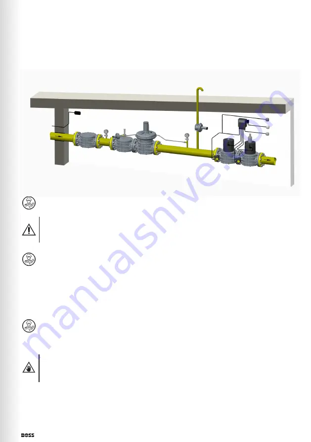
EXAMPLE 2 (Burner Gas Train)
1. Gas filter
2. OPSO shut off valve
3. Pressure regulator
4. Minimum pressure switch
5. 355AA... fast opening automatic
solenoid valve
6. Maximum pressure switch
7. Slow opening automatic solenoid valve
8. External reset
9. Burner control
10. Valve proving system
11. Relief valve
12. Pressure gauge and relative button
13. Gas detector
Summary of Contents for 355AA
Page 13: ...13 EN fig 2 DN 32 DN 40 DN 50 ...
Page 14: ...14 EN fig 3 DN 65 DN 80 DN 100 ...
Page 15: ...15 EN fig 4 DN 125 DN 150 ...