background image

13

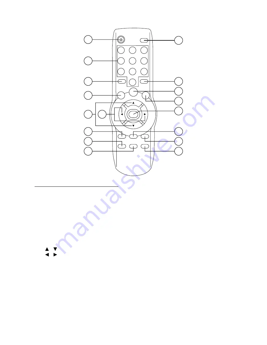
REMOTE CONTROL HANDSET

2

11

8

9

10

16

5

6

7

14

13

15

12

17

4

3

1

CONTROL & FUNCTION KEYS

1.

POWER = Press POWER to turn the unit ON or OFF

2.

TV/AV

= Switch between TV/AV1/AV2

3.

0 - 9

= Numeric buttons, press to select the corresponding channel

4.

-/--

= Digital selecting button, cooperatively used with numeric buttons

5.

MUTE

= Press to mute the sound.  When release the button, the screen will 

display VOLUME XX for about 4 seconds, and this is the AUDIO level
setting value of the TV unit.  The users may not mind it, and that adjust
the volume level by VOL + and VOL – buttons.

6.

SCAN

= Scan 1.5 seconds of each channel

7.

MENU

= Display the main menu to adjust picture and set program and control system

8.

    /

= In case of MENU mode, the buttons are used to select the sub-menus

9.

    /

= In case of MENU mode, the buttons are used to adjust the selected item

10. VOL +

= Increase the volume level

11. VOL –

= Decrease the volume level

12. PICT

= Select picture mode.  There are five modes:  STANDARD, SHARP, 

BRIGHT, MEMORY and MILD.  The MEMORY mode is user-defined
mode and the others are preset mode.

13. RETURN = Switch between last viewed channel and this time viewed channel
14. CH +

= Choose channel upward

15. CH –

= Choose channel downward

16. DSP

= Press to display the channel number and SYSTEM status.  In AV mode,

there is no SOUND SYSTEM display

17. SORT

= Program sorting button, cooperatively used with digital selecting button

and numeric buttons

Summary of Contents for BV500

Page 1: ...BV 500 AUDIO SYSTEMS R OWNER S MANUAL IN DASH LCD MONITOR TV TUNER AM FM RECEIVER CD CHANGER CONTROLLER ...

Page 2: ... as a part of your multimedia For best results please consult a professional mobile electronics installer for application advice or troubleshooting To guarantee top performance we recommend using The Link installation accessories such as RCA interconnects power cables and speaker wire Thank you for choosing Audio Systems products for your mobile entertainment system We can t change the world but w...

Page 3: ...t where it does not get in the driver s way and cannot injure the passenger if there is a sudden stop like an emergency stop If installation angle exceeds 30 from horizontal the unit might not give its optimum performance Avoid installing the unit where it would be subject to high temperature such as from direct sunlight or from hot air from the heater or where it would be subject to dust dirt or ...

Page 4: ...tion INSTALLING THE DISPLAY UNIT Before installing the display unit please remove the backstrap screw and wiring harress This unit can be properly installed either from front convertional DIN Front mount or rear DIN Rear mount installation utilizing threaded screw holes at the sides of the unit chassis For details refer to the following illustrated installation methods DIN FRONT MOUNT Installing t...

Page 5: ...levers upward and out to makes it possible to remove the unit DIN REAR MOUNT Installation using the screw holes on the both sides of the unit Fastening the unit to the factory radio mounting bracket 1 Select a position where the screw holes of the bracket and the screw holes of the main unit become aligned are fitted and tighten the screws at 2 places on each side Use either truss screws 5 x 5mm o...

Page 6: ...THE SCREEN DISPLAY 1 Press release button then carefully pull the monitor out toward you 2 Turning the display upward 3 Adjust the viewing angle as shown Adjustment should be made slowly using minimal force Release Button 5 ...

Page 7: ...e the unit turn the display to the center position then fold it down The monitor must be centered and folded down before the unit can be closed properly 5 Push the panel in until is clicks into the locked position ...

Page 8: ...ont of the tuner module is in the correct position If not move the A B switch to the other position RADIO TV MAIN UNIT VIEW FROM REAR TV DIVERSITY ANTENNA INPUT CDC INPUT GREY TV CONTROL GREY BLACK TV DIVERSITY ANTENNA INPUT RADIO ANTENNA INPUT TO CD CHANGER BLUE WHITE POWANT REAR Rch SPK VIOLET VIOLET BLACK FRONT Rch SPK GREY GREY BLACK REAR Lch SPK GREEN GREEN BLACK FRONT Lch SPK WHITE WHITE BLA...

Page 9: ...8 OPERATION 23 26 27 22 1 28 4 25 9 10 24 15 4 12 19 20 21 18 17 3 14 6 8 5 1 11 7 16 2 13 29 ...

Page 10: ... and 8 buttons Fader Press SEL button 6 for four times Adjust sound balance between front and rear speakers using 7 and 8 buttons SELECTING PLAYING MODE When the screen display is drawn in press MOD button 12 to select desired playing mode between radio and CDC When the screen display is drawn out the unit would automatically switch into TV mode By pressing MOD button 12 you can select desired pla...

Page 11: ...n display SELECTING MEMORY Press preset memory buttons 15 to preset stations at tuner mode With this system a total of 30 stations can be stored in the memory of six buttons The stations might be FM1 FM2 FM3 AM1 and AM2 band The operation is as below Store in Memory Press and hold desired memory location button for several seconds The current listening station will be stored into the number button...

Page 12: ...ly repeat all tracks on the current disc Press it the third time to stop repeating PREVIEW ALL TRACKS Press SCN button 20 to play the first several seconds of each track on the current disc Press it again to stop intro and listen to track RANDOM PLAY Press RND button 21 to play all tracks on the current CD in random order Press it again to cancel the mode CD CHANGER SETTING Reference the figure wh...

Page 13: ...s no SOUND item The setting method is the same with that in TV mode Note In the menus except TUNER MENU if you don t operate over 6 seconds the screen display will disappear SELECTING CHANNEL Press CH button 9 or CH button 10 to choose channel upward or downward PROGRAM SCANNING Press SCAN button 27 SCAN OFF will display on the lower left corner of the screen Press it again the screen will display...

Page 14: ...annel 7 MENU Display the main menu to adjust picture and set program and control system 8 In case of MENU mode the buttons are used to select the sub menus 9 In case of MENU mode the buttons are used to adjust the selected item 10 VOL Increase the volume level 11 VOL Decrease the volume level 12 PICT Select picture mode There are five modes STANDARD SHARP BRIGHT MEMORY and MILD The MEMORY mode is ...

Page 15: ...Ohms Current Consumption 10 Amperes max Tone Controls Bass at 100 Hz 10 dB Treble at 10 KHz 10 dB TV Monitor Screen Size 5 0 TFT Resolution 960 x 234 dots TV Sensitivity 45 dBµV PD max CH25 in average RADIO FM Frequency Coverage 87 5 to 107 9 MHz Sensitivity 30 dB S N 6 µV Image Rejection 45 dB Stereo Separation 25 dB AM Frequency Coverage 530 to 1710 KHz Sensitivity 20 dB S N 35 dB Image Rejectio...

Page 16: ...88 T0900 14 AUDIO SYSTEMS 3451 Lunar Court Oxnard CA 93030 www bossaudio com R ...

Reviews: