24
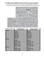
LT 6403 and LT 9403 Crossover Board Layout Diagram
The LT 6403 and LT 9403 loudspeakers both use the same bare board for their crossover
assemblies. The only differences are the components populating the board. See the table below.
Reference Designator
LT 6403 Crossover PCB
Component Values
LT 9403 Crossover PCB
Component Values
Capacitors
C1
40uF / 250V
40uF / 250V
C2
10uF / 200V
4.7uF / 200V
C3
40uF / 200V
40uF / 200V
C4
60uF / 200V
Jumper
C5
4.7uF / 100V
4.7uF / 100V
C6
3.9uF / 100V
3.9uF / 100V
C7
20uF / 100V
20uF / 100V
C8
20uF / 100V
20uF / 200V
C9
5uF / 100V
5uF / 200V
Inductors
L1
6mh / 0.8 Ohms
6mh / 0.8 Ohms
L2
9mh / 1.1 Ohms
32mh / 1.6 Ohms
L3
.68mh / 0.7 Ohms
.68mh / 0.7 Ohms
L4
.27mh / 0.4 Ohms
.27mh / 0.4 Ohms
L5
1.2mh / 0.3 Ohms
Jumper
L6
.68mh / 0.6 Ohms
.68mh / 0.6 Ohms
L7
.82mh / 0.7 Ohms
.82mh / 0.7 Ohms
L8
.56mh / 0.6 Ohms
.56mh / 0.6 Ohms
Resistors
R1 10
Ohm
/
15
Watt
Jumper
R2
20 Ohm / 15 Watt
4 Ohm / 15 Watt
R3
10 Ohm / 15 Watt
20 Ohm / 15 Watt
Summary of Contents for LT 6400
Page 12: ...12 11 10 8 9 2 3 4 5 6 7 1 Figure 5 Panaray LT 6403 Loudspeaker Exploded View ...
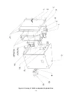
Page 14: ...14 Figure 6 Panaray LT 6400 Loudspeaker Exploded View ...
Page 16: ...16 Figure 7 Panaray LT 9403 Loudspeaker Exploded View 1 3 4 5 6 7 2 10 11 8 9 ...
Page 18: ...18 Figure 8 Panaray LT 9400 Loudspeaker Exploded View ...
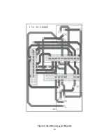
Page 23: ...23 Figure 9 Input Board Layout Diagram ...
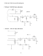
Page 26: ...26 LT 6403 and LT 9403 Crossover Wiring Diagrams ...


