


4.1
The appliance is not suitable for external installation unless
a suitable enclosure is provided.
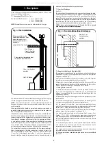
4.2
The appliance should be positioned on a non-combustible
solid base as near to the flue location point as possible. Care
should be taken to ensure that the appliance is level; use
packing at the corners where necessary.
4.3
When fitting a LLD or RS model, the rear of the appliance
must be positioned against an external wall such that the flue
terminal can safely discharge the flue gases as described in
Section 7.
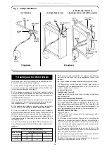
4.4
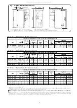
The following clearances must be left to allow access for
installation and servicing:
(a) Above - 300mm
(b) In front - 600mm
(c) Right and left hand side – sufficient for panel
removal and access to pipe connections where
required.
See Figs. 2 and 3.
For installation and servicing of the appliance the cabinet should
be removed as follows:
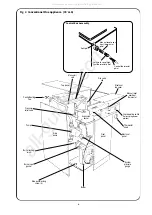
5.1
Remove the cabinet top panel by lifting squarely upwards to
release the four ball stud connections.
5.2
Remove the front panel by pulling the bottom of the panel
forwards to release the ball studs and lifting the panel upwards
and forwards to release from its supporting ledge.
5.3
The side panels are removed by firstly following procedures
5.1 to 5.2 as described above, then remove screw (A) from the
side panel base and the three screws located in the upper flange
of each side panel. Ease the panel clear of the electrical control
box and slide forwards to release from the locating lugs on the
base plate.
5.4
The control box can be removed by undoing the four screws
in the top access cover and then removing the wing nut on the
underside of the control box. The thermostat phials should be
carefully removed from the phial pocket and the control box
placed in a safe place taking care not to kink the thermostat
capillary tubes.
5.5
On the RS balanced flue model, remove the burner box
cover by pulling forwards to release the ball studs. This will be
found easier by pulling on one side of the handle first to release
two of the ball studs and then repeating on the other side. Take
care not to pivot the remaining two ball studs too far around as
this will cause damage to the spring clips.
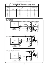
OPEN FLUE MODEL ( CF/LLD )
This includes conventional flue and standard low level and high
level horizontal discharge kits.
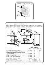
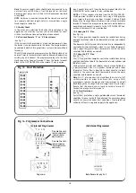
6.1
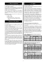
In order to ensure clean and efficient combustion an
adequate supply of air must be delivered to the combustion
chamber. To provide sufficient air a suitable inlet should be
provided into the room or space in which the boiler is situated,
the sizes of which are given in Table 5. An air brick or other form
of continuous air supply may have to be built into the
installation in order to ensure an adequate supply of air.
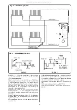
6.2
If the appliance is to be installed in a confined space or com-
partment two air vents are required, one at high level and one at
low level. The minimum free area of each vent is given in Table 6
and depends whether the air is taken from another room or
from outside the building. Where the air is taken from another
room that room must contain an air inlet as described in 6.1.
6.3
There must be sufficient clearance around the appliance to
allow proper circulation of ventilation air. The clearances
required for installation and servicing will normally be adequate
for ventilation. See Section 4.4.
ROOM SEALED BALANCED FLUE MODEL ( RS )
6.4
The appliance does not require a separate vent for
combustion air.
6.5
Installation in cupboards or compartments require
permanent vents for cooling purposes, one at high level and one
at low level, either direct to outside air or to a room. Both vents
must pass to the same room or be on the same wall to the
outside air. The minimum air vent free area is given in Table 7.
6.6
There must be sufficient clearance around the appliance to
allow proper circulation of ventilation air. The clearances
required for Installation and Servicing will normally be adequate
for ventilation. See Section 4.4.
6. Air Supply
5. Removal of the Cabinet
4. Siting the Appliance
5
Table 6. Minimum Air Vent Free Area for Open Flue
appliances installed in a compartment.
Appliance
Ventilation to room or
Ventilation to outside
model
internal space
High Level
Low Level
High Level
Low Level
12/14
154cm
2
231cm
2
77cm
2
154cm
2
15/19
209cm
2
314cm
2
105cm
2
209cm
2
20/25
275cm
2
413cm
2
138cm
2
275cm
2
Table 7. Minimum Air Vent Free Area for Room Sealed
appliances installed in a compartment.
Appliance
Ventilation to room or
Ventilation to outside
model
internal space
High Level
Low Level
High Level
Low Level
12/14
154cm
2
154cm
2
77cm
2
77cm
2
15/19
209cm
2
209cm
2
105cm
2
105cm
2
20/25
275cm
2
275cm
2
138cm
2
138cm
2
APPLIANCE
AREA OF AIR INLET
cm
2
in.
2
12/14
77
12
15/19
105
16.5
20/25
138
21.5
Table 5. Minimum Combustion Air Inlet Free Area for
Open Flue appliances
All manuals and user guides at all-guides.com