background image

AutoDome Power Supply Boxes

Installing the Power Supply Box | en

19

Bosch Security Systems, Inc.

Installation Guide

F.01U.250.895 | 1.0 | 2011.08

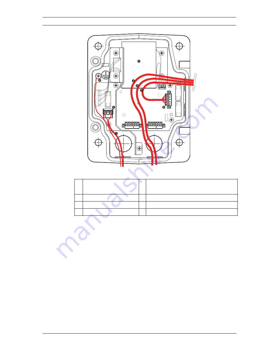
Figure 2.3

VG4-A-PSU1 or VG4-A-PSU2 Power Supply Box

1 24/120/230 VAC 

Power In

5 Coax, UTP Video, or Ethernet Wire

(Ethernet for VG5 700 Series only)

2 P101 Connector

6 Control Wire

3 Ground Connection

7 24 VAC Power Out

4 Transformer

8 P107 Connector

GND TXD 


RXD    


C+    


C-

GND TXD 


RXD    


C+    


C-

P101

P106

P105

P107

XF102

XF103

XF101

5 4 3 2 1

J

J

J103

J102

J101

(LED)

HTR                  DOME

24V     NC    24V

(FUSE

)

(FUSE

)

(FUSE

)

Summary of Contents for VG4-A-PSU0

Page 1: ...AutoDome Power Supply Boxes VG4 A PSU0 VG4 A PSU1 VG4 A PSU2 en Installation Guide ...

Page 2: ......

Page 3: ... Notices 8 1 4 UL certification 10 1 5 Bosch notices 10 2 Installing the Power Supply Box 12 2 1 Unpacking 12 2 1 1 Parts List 12 2 1 2 Optional Parts List 12 2 1 3 Description 13 2 1 4 Tools Required 13 2 2 Pre installation Check List 13 2 3 Mount the Power Supply Box 15 2 3 1 Attach Cover Door 16 2 4 Route Wires and Attach Connectors 18 2 4 1 Methods for Routing Wires 18 2 4 2 Wiring the Power S...

Page 4: ... to Transmit Video and Control 27 3 3 4 Using Multi mode Fiber Optic to Transmit Video and Control 27 3 3 5 Using a Fiber Optic Ethernet Media Converter to Transmit Video and Control 28 3 4 Control only Cables 29 3 4 1 Controlling the AutoDome via Biphase 29 3 4 2 Controlling the AutoDome via the RS232 Protocol 30 3 4 3 Controlling the AutoDome via the RS485 Protocol 32 3 5 Fiber Optic Module with...

Page 5: ...nently hazardous situation such as Dangerous Voltage inside the product If not avoided this will result in an electrical shock serious bodily injury or death WARNING Medium risk Indicates a potentially hazardous situation If not avoided this could result in minor or moderate bodily injury CAUTION Low risk Indicates a potentially hazardous situation If not avoided this could result in property dama...

Page 6: ...a classified as a wet location To reduce the risk of fire or electrical shock do not expose this unit to rain or moisture 3 Object and liquid entry Never push objects of any kind into this unit through openings as they may touch dangerous voltage points or short out parts that could result in a fire or electrical shock Never spill liquid of any kind on the unit Do not place objects filled with liq...

Page 7: ...al codes Class 2 power levels Do not ground the supply at the terminals or at the unit s power supply terminals If unsure of the type of power supply to use contact your dealer or local power company 7 Servicing Do not attempt to service this unit yourself Opening or removing covers may expose you to dangerous voltage or other hazards Refer all servicing to qualified service personnel 8 Damage req...

Page 8: ...by Bosch could void the warranty or in the case of an authorization agreement authority to operate the equipment 1 3 Important Notices U S A models only Section 810 of the National Electrical Code ANSI NFPA No 70 provides information regarding proper grounding of the mount and supporting structure grounding of the coax to a discharge unit size of grounding conductors location of discharge unit con...

Page 9: ... SELV All the input output ports are Safety Extra Low Voltage SELV circuits SELV circuits should only be connected to other SELV circuits Because the ISDN circuits are treated like telephone network voltage avoid connecting the SELV circuit to the Telephone Network Voltage TNV circuits System ground Safety ground System video ground is indicated by the symbol Safety power ground is indicated by th...

Page 10: ...er Underwriter Laboratories Inc UL has not tested the performance or reliability of the security or signaling aspects of this product UL has only tested fire shock and or casualty hazards as outlined in UL s Standard s for Safety for Information Technology Equipment UL 60950 1 UL Certification does not cover the performance or reliability of the security or signaling aspects of this product UL MAK...

Page 11: ...cordingly Note This manual has been compiled with great care and the information it contains has been thoroughly verified The text was complete and correct at the time of printing The ongoing development of the products may mean that the content of the user guide can change without notice Bosch Security Systems accepts no liability for damage resulting directly or indirectly from faults incomplete...

Page 12: ...eturning the unit for service Save it for possible future use 2 1 1 Parts List The following table lists the parts included with one of the following power supply boxes 2 1 2 Optional Parts List The following table lists the optional equipment for use with the power supply boxes Note The fiber optic kits are mounted inside the power supply box Refer to the individual kit for installation instructi...

Page 13: ...kaging 2 1 4 Tools Required Small straight blade screwdrivers 2 5 mm 0 1 in 3 1 mm 1 8 in Medium straight blade screwdriver No 1 and No 2 Phillips screwdrivers Socket wrench and 9 16 in socket Power drill Water tight conduits and fittings that meet NEMA 4 standards 2 2 Pre installation Check List 1 Determine the location and distance for the power supply box based on its voltage and current consum...

Page 14: ...ntrolling the AutoDome via the RS485 Protocol page 32 for instructions on configuring the AutoDome to accept these protocols 5 Purchase the appropriate mounting hardware to use depending on the location of power supply box WARNING External interconnecting cables are to be installed in accordance to NEC ANSI NFPA70 for US application and Canadian Electrical Code Part I CSA C22 1 for CAN application...

Page 15: ... template supplied in the packaging box to locate the four 4 mounting holes for the power supply box 2 Drill four 4 holes for the mounting anchors If installing outdoors apply a weatherproof sealant around each hole at the mounting surface 3 Place the power supply box into the optional trim skirt 4 Secure the power supply box to the wall using four 4 corrosion resistant stainless steel studs not i...

Page 16: ...then rotate it behind the hinge pin stop The power box cover door provides a hinge pin stop to hold the bottom hinge open while attaching the door Figure 2 2 Align Cover Door Hinge to Power Box 2 Open the top hinge by pushing its pin lever outward and holding it open Note Both hinge pins must be fully compressed to open unlock the female hinges of the cover door before proceeding to the next step ...

Page 17: ...x and align its hinges 4 When the hinges are aligned release the top hinge pin to engage its mating hinge on the power box Then release the bottom hinge pin from the hinge pin stop to complete attaching the cover door to the power supply box NOTICE After all wiring is complete close the cover door and tighten the two 2 captive screws on the cover door to 10 12 N m 90 105 in lbs to ensure the power...

Page 18: ...s to route the video control and alarm wires One is to route the video control and alarm wires through the conduit fitting on the right front side of the power supply box and out to the AutoDome Arm Mount or to the Interface Board for Pipe and Roof Parapet mounts WARNING External interconnecting cables are to be installed in accordance to NEC ANSI NFPA70 for US application and Canadian Electrical ...

Page 19: ...r VG4 A PSU2 Power Supply Box 1 24 120 230 VAC Power In 5 Coax UTP Video or Ethernet Wire Ethernet for VG5 700 Series only 2 P101 Connector 6 Control Wire 3 Ground Connection 7 24 VAC Power Out 4 Transformer 8 P107 Connector GND TXD RXD C C GND TXD RXD C C P101 P106 P105 P107 XF102 XF103 XF101 5 4 3 2 1 J J J 103 J102 J101 LED HTR DOME 24V NC 24V FUSE FUSE FUSE ...

Page 20: ...Box Connected to Pipe Interface Board VG4 A PSU1 PSU2 Pipe Interface Board 1 24 12 230 VAC Power In 7 P101 Connector 2 P101 Connector 8 P107 Connector 3 Ground Connection 9 24 VAC Power In to AutoDome 4 Transformer 10 Earth Ground 5 24 VAC Power Out 11 24 VAC Power In to AutoDome 6 P107 Connector 12 24 VAC Power In to Heater 13 24 VAC Power In to Heater 14 AutoDome Power 15 Heater Power GND TXD RX...

Page 21: ...e 23 4 Analog AutoDome If you are using UTP for video route the UTP cable out to where the AutoDome will be mounted Refer to Section 3 Cable and Wire Standards page 24 for fiber optic specifications 5 IP AutoDome Route the Ethernet cable out to where the AutoDome will be mounted Refer to Section 3 Cable and Wire Standards page 24 for specifications 6 Route the low power 24 VAC wires from the right...

Page 22: ...ting 4 24 VAC to Dome Interface Board 8 Control Data and Video In Out 3 4 in 20 mm NPS Fitting CONTROL TO DOM E M M CONTROL IN OUT GND TXD RXD C C P101 1 2 3 6 5 4 3 2 1 3 P106 P105 P107 XF102 XF103 XF101 5 4 3 2 1 J103 J103 J J 103 J102 1 1 1 1 1 J101 1 1 1 1 1 1 1 1 1 1 1 1 1 1 1 1 1 1 1 1 1 1 1 1 1 1 1 1 1 1 1 LED 6 5 4 3 2 1 GND TXD RXD C C HTR DOME FUSE FUSE FUSE 24V NC 24V WARNING Fuse repla...

Page 23: ...4 Pin 5 Pin 6 Ground Grounding Screw P101 115 230 VAC or 24 VAC Power In Line NC Neutral P1051 Control to Dome Fiber Optic Model C Biphase C Biphase Earth Ground RXD RS 232 485 TXD RS 232 485 Signal Groun d P1061 Control In Out Optional C Biphase C Biphase Earth Ground RXD RS 232 485 TXD RS 232 485 Signal Groun d P107 24 VAC Power to Dome Plug Dome 24 VAC Dome 24 VAC Earth Ground Heater 24 VAC Hea...

Page 24: ... VAC Copper Wire To comply with local codes 24 V to AutoDome VA Watts 14 AWG 2 5 mm 16 AWG 1 5 mm 18 AWG 1 0 mm AutoDome 100 Indoor 14 7 5 248 m 813 ft 156 m 512 ft 98 m 322 ft AutoDome 100 Outdoor 47 43 5 74 m 242 ft 46 m 152 ft 29 m 96 ft AutoDome 600 Indoor 27 15 129 m 422 ft 81 m 265 ft 51 m 167 ft AutoDome 600 Outdoor1 55 51 63 m 207 ft 40 m 130 ft 25 m 82 ft AutoDome 700 Indoor 35 19 99 m 32...

Page 25: ... you are using coaxial cable to transmit video and data between the AutoDome and the head end you must use the coax cable with ferrite included in the AutoDome packaging You must connect the incoming coax cable from the head end to the jack female end on the ferrite cable and connect the plug end male connector of the ferrite cable to the AutoDome s coax connector Cable Compensation Maximum Distan...

Page 26: ...a Bosch 2 way communication protocol that allows remote control configuration and updates over a passive UTP cable VG5 100 and 600 Series AutoDomes feature cable compensation or Pre Comp which extends the normal range of control from the head end The following figure illustrates the connections necessary to transmit video and control over a UTP cable Figure 3 1 Video and Control over UTP WARNING D...

Page 27: ...ultimode fiber CAUTION Ethernet connections must be made to non exposed indoor networks only Cable Type CAT 5E or CAT 6 Ethernet Maximum Distance 100 m 328 ft Bandwidth 10 Base T 100 Base TX Terminal Connector RJ45 Female WARNING Do not connect a coaxial cable while the RJ45 Ethernet cable is connected Multimode Fiber Type 50 125 µm 62 5 125 µm low loss multimode glass fiber Maximum Distance 4 km ...

Page 28: ...e fiber SMF models with a single SC connector or dual fiber with an LC connector Refer to the VG4 SFPSCKT Fiber Optic Media Converter Installation Guide Ethernet Media Converter Data Interface Ethernet Data Rate 10 100 Mbps IEEE 802 3 Compliant Full Duplex or Half Duplex Electrical Port Full Duplex Optical Port Fiber Type MMF 50 125 µm MMF For 50 125 µm fiber subtract 4 dB from the specified optic...

Page 29: ...ermination resistor between the Biphase C and C terminals The figure below illustrates the connections necessary for Biphase operation Figure 3 2 Connections for Biphase Operation CAUTION The Biphase shield must be connected to the head end only Cable Type STP Shielded Twisted Pair Distance 1524 m 5000 ft Belden 8760 recommended Transmission Rate 31 25 KHz Gage 1 02 mm 18 AWG Termination 100 Ω Ter...

Page 30: ...ngle ended 50 ft cable limit RS232 is a common single ended communication protocol used for control Data transmission via 3 wires TDX RXD common is from one transmitter to one receiver at relatively slow baud rates up to 57 6 Kbaud and short distances up to 50 ft 1 C Biphase 9 Dome 3 2 C Biphase 10 Dome 2 3 Earth Ground 11 Dome 1 4 RxD 12 Head End Biphase 5 TxD 13 C Biphase 6 Signal Ground 14 C Bi...

Page 31: ...arity Note To access the CPU switch you must remove the bubble from the pendant housing Wire Type 3 wire TXD RXD common Distance 15 m 50 ft Maximum Baud Rate 57 6 Kb Voltage 15 V Termination 100 Ω Slide Switch Away from LEDs factory default 1 C Biphase 7 AutoDome Data In Out 2 C Biphase 8 P105 P106 Connector in Power Supply Box 3 Earth Ground 9 Head End RS232 4 RxD 10 TxD 5 TxD 11 RxD 6 Signal Gro...

Page 32: ...OTICE The wire shield must be tied to signal at both ends if 2 wire twisted pair is used After connecting the wires for RS485 operation make sure the slide switch on the main board to the camera head is positioned toward the LEDs default CAUTION Bosch recommends that multiple RS485 connections be arranged as a connected series of point to point multi dropped nodes as a line or as a bus It is not r...

Page 33: ...Position of CPU Switch for RS485 Operation camera module not shown for clarity Note To access the CPU switch you must remove the bubble from the pendant housing 1 C Biphase 7 AutoDome Data In Out 2 C Biphase 8 P105 P106 Connector in Power Supply Box 3 Earth Ground 9 Head End RS485 4 RxD 10 Data 5 TxD 11 Data 6 Signal Ground 12 Ground 1 Switch Location 2 LEDs 3 RS485 4 CPU Module 100 Ω ...

Page 34: ... Connecting to an LTC 4629 Head End Data Video Transceiver 1 Connect the RS232 cable TxD from the controller to the RS232 RxD port pin 1 of the LTC 4629 2 Connect the ground wire of the controller to Pin 2 on the LTC 4629 3 5 2 Configuring the VG5 AutoDome 1 Disconnect the power to the VG4 power supply unit then open the unit 2 Remove the green Serial Communications wire from the P106 connector 3 ...

Page 35: ...Ensure that the VG5 AutoDome is set to receive RS232 commands Remove the bubble from the VG5 AutoDome housing Locate the protocol switch on the CPU board Ensure that the protocol switch is in the left position for RS232 operation Figure 3 9 Position of CPU Switch for RS232 Operation 1 Green RxD wire connected to C 2 Blue Ground wire connected to C 1 Switch Location 2 LEDs 3 Move Switch to the left...

Page 36: ...over a network The audio signal is transmitted one way and in sync with the video signals Audio Line Input Specifications Wire Specifications Max Input Voltage 5 5 Vpp Impedance 9K Ω Sample Rate 8 K Hz 16 Bit mono Shield Bare copper braid 95 coverage Internal gain level adjustment is available Wire Type Coax3 recommended Distance 10 m 33 ft Gage 22 AWG to Biphase connector P105 P106 Shield Bare co...

Page 37: ...phase C input terminal 3 Connect the audio signal ground to the Biphase C input terminal The following figure illustrates the connections for audio over an IP network Figure 3 10 Connections for audio over an Ethernet network 1 C Biphase 7 AutoDome Data In Out 2 C Biphase 8 P105 P106 Connector 3 Earth Ground 9 Audio Out 4 RxD 5 TxD 6 Signal Ground NOTICE Refer to the VG5 700 Series AutoDome User M...

Page 38: ...38 en Cable and Wire Standards AutoDome Power Supply Boxes F 01U 250 895 1 0 2011 08 Installation Guide Bosch Security Systems Inc ...

Page 39: ......

Page 40: ...Bosch Security Systems Inc 850 Greenfield Road Lancaster PA 17601 U S A www boschsecurity com Bosch Security Systems Inc 2011 ...

Reviews: