background image

24

Información sobre el calentador de agua

Tronic 3000T – 6 720 801 072 (2018/04)

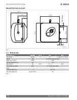
Modelos ES8 (Instalación horizontal) 

Fig. 7

2.3

Datos técnicos

Datos técnicos

Unidades

ES 2.5

ES 4

ES 8

Capacidad

galones

2.7

4.0

7.0 (Hor.) / 5.1 (Vert.)

Voltaje

VAC

110/120 para cada modelo

Potencia a 120 VAC

Watts

1440

Presión de agua máxima

psi

150

Peso (vacío)

Lbs

15.5 

17.3

29.5

Intensidad de corriente

Amps

12.0 para cada modelo

Fases

1

Gama de temperatura

°F

65 - 145

Tasa de recuperación

galones/hora

6.8

Tab. 2

14 ½”

4 ½”

8 ½”

17.6”

17.6”

6720801072-05.1V

M

A

X

M

I

N

O

FF

IDE

A

L

3”

11.4”

¾

NPT

MALE

1”

Summary of Contents for Tronic 3000T ES 2.5

Page 1: ...Use this manual for installations in the United States of America Utilice este manual para las instalaciones en los Estados Unidos de América 2 Installation Manual and Operating Instructions 19 Instrucciones de Instalación y Funcionamiento NSF ANSI 61 ...

Page 2: ...nnections 8 3 3 Closed system thermal expansion 9 3 4 Electrical connections 10 4 Use 10 4 1 Starting and testing 10 4 2 Temperature setting 11 5 Maintenance 11 5 1 Removing the cover 11 5 2 Draining the heater 11 5 3 Inspecting the anode rod 11 5 4 Removing the heating element 12 5 5 Descaling the heating element 12 6 Replacement of parts 13 6 1 Changing the anode rod 13 6 2 Changing the heating ...

Page 3: ...ed or dropped This water heater should be serviced only by qualified service personnel Contact a service person for examination repair or adjustment Failure to inspect the anode rod at least once a year could causethetanktofailandleak Thisconditionisnotcovered under the manufacturer s warranty Any water heater should be installed in such a manner that if it should leak the resulting flow of water ...

Page 4: ... electrical appliance connected to the hot water system If hydrogen gas is present there will probably be an unusual sound such as air escaping through the pipe as the water begins to flow There should be no smoking or open flame near the faucet at the time it is open MAX M I N OFF I D E A L 6720801072 07 1V CAUTION Any water heater should be installed in such a manner that if it should leak the r...

Page 5: ...let NPT male 3 Thermostat 4 Temperature pressure relief valve discharge line to drain 5 NPT female tapping for relief valve 6 Hot water outlet NPT male 7 NPT male plug 8 NPT female tapping for tap Models ES8 Vertical installation Fig 4 1 Temperature pressure relief valve NPT male 2 Cold water inlet NPT male 3 Thermostat 4 Temperature pressure relief valve discharge line to drain 5 NPT female tappi...

Page 6: ...18 04 2 2 Dimensions Models ES2 5 and ES4 Vertical installation only Fig 5 Models ES8 Horizontal installation only Fig 6 10 6 3 13 9 3 2 2 3 13 NPT male 13 5 3 8 1 6720801072 04 1V ES2 5 ES4 14 4 8 6720801072 06 1V 17 6 MIN OFF M AX IDEAL 17 6 1 11 4 NPT MALE 2 6 ...

Page 7: ... ES 4 ES 8 Capacity gallons 2 7 4 0 7 0 Hor 5 1 Vert Voltage VAC 110 120 for each model Power at 120 VAC Watts 1440 Maximum water pressure psi 150 Weight empty Lbs 15 5 17 3 29 5 Amperage Amps 12 0 for each model Phases 1 Temperature range F 65 145 Recovery rate gallons hour 6 8 Table 2 14 4 8 17 6 17 6 6720801072 05 1V M A X MIN OFF IDEAL 3 11 4 NPT MALE 1 ...

Page 8: ...See location of T P relief valve in Fig 7 Vertical installation If you wish to install the unit vertically with the piping connections on top Install supplied brass plug into tap on side of water heater The supplied Temperature and Pressure Relief Valve will need to be installed on top See location of T P relief valve in Fig 5 and Fig 6 Caution The ES2 5 and ES4 water heaters are designed to be in...

Page 9: ...mbing Code 3 3 Closed system thermal expansion Periodic dischargeof thetemperatureand pressure relief valve or failure of the element gasket may be due to thermal expansion in a closed water supply system The water utility supply meter may contain a checkvalve backflow preventer or water pressure reducing valve which will create a closed water system Duringtheheatingcycleofthe waterheater the wate...

Page 10: ...eans of disconnection for all non grounded conductors must be provided that is within sight of the appliance REF NEC 422 31 Fig 8 1 Cable housing internal to the unit 2 Wiring 3 Protection ring for wiring 4 Additional grounding cable AWG16 minimum length 152mm 5 Junction box left cover 6 Nº3 self tapping screw for junction box covers fixing with lock washer or serrated head 7 Junction box right co...

Page 11: ...it can also be emptied by Siphon through the inlet side hose Keep a hot water faucet open while siphoning or If the heater has been installed with rigid piping Siphon the water out through any lower service valve on the inlet side Keep a hot water faucet open while siphoning the water out 5 3 Inspecting the anode rod The purpose of the anode rod Fig 12 N is to protect the tank against corrosion It...

Page 12: ... element retaining nuts F Remove thermostat temperature sensor from well B located on the element assembly Remove the element G Fig 10 Fig 11 5 5 Descaling the heating element Scale deposits can affect the heating capability of the element Heavy scale can even cause damage to the element The element can be descaled either chemically or manually Soak the element in white vinegar or other descaling ...

Page 13: ...gasket and element are positioned correctly Tighten the retaining nuts and make the wire connections Ensure that the thermostat temperature sensor is inserted into the well located on the element assembly and secured with black rubber grommet Refill tank with water before restoring power 6 3 Changing the thermostat Turn off power supply Disconnect the 2 wire connectors on thermostat Loosenthetwobr...

Page 14: ...ould be replaced if readings are outside these values Light not on If the light does not come on but water gets hot check for faulty bulb Check high limit reset button follow steps in section 7 1 Brown water Brown or rusty water indicates a spent anode rod and possible deterioration of the tank body Inspect the tank for leaks Check anode rod see section on changing the anode rod Odor in water Smel...

Page 15: ...sresetbutton B with the tip ofa ballpointpen or similar object Fig 13 A click indicates the reset was tripped Reconnect power IMPORTANT Check the operation of the thermostat Turn temperature dial from high to low If the red light does not go off on low setting Turn off power supply and call a service person to replace the thermostat If the red light does go off the thermostat is working well Place...

Page 16: ...4 443 0 ES 2 5 ES 4 ES 8 14 PLASTIC COVER 8 738 704 446 0 ES 2 5 ES 4 ES 8 18 KNOB 8 738 704 444 0 ES 2 5 ES 4 ES 8 22 VALVE T P 8 738 704 445 0 ES 2 5 ES 4 ES 8 23 MAGNESIUM ANODE D 14 L 155 M4 8 738 704 447 0 ES 2 5 ES 4 MAGNESIUM ANODE D 16 L 195 8 738 704 448 0 ES 8 31 LOCK NUT M6 8 738 704 449 0 ES 2 5 ES 4 ES 8 33 GASKET WITH 4 BOLTS 8 738 704 450 0 ES 2 5 ES 4 ES 8 38 SIGNAL LAMP CAP 8 738 ...

Page 17: ...nce See the Installation Manual for installation and maintenance information 2 Failure or malfunction resulting from contaminated or corrosive air or liquid supply the addition of unapproved chemicals operation at abnormal temperatures pressures or flow rates or any attachment accessory or component not authorized and approved by BTC See the Installation Manual for installation and maintenance inf...

Page 18: ...18 Tronic 3000T 6 720 801 072 2018 04 Notes ...

Page 19: ...ería 25 3 3 Expansión térmica en un sistema cerrado 26 3 4 Conexiones eléctricas 27 4 Uso 27 4 1 Puesta en marcha y pruebas 27 4 2 Ajuste de la temperatura 28 5 Mantenimiento 28 5 1 Quitar la tapa 28 5 2 Drenado del calentador 28 5 3 Inspección de la barra del ánodo 28 5 4 Desmontaje del elemento de calentamiento 29 5 5 Descalcificación del elemento de calentamiento 30 6 Sustitución de piezas 30 6...

Page 20: ... aparato eléctrico es necesaria una estrecha supervisión cuando la unidad sea utilizada por niños No utilice este calentador de agua si el cable o el enchufe están dañados si no funciona correctamente o si ha sido dañado o sufrido una caída Solamente personal de servicio calificado debe dar servicio a este calentador de agua Para todo examen reparación o ajuste de la unidad llame a un técnico de s...

Page 21: ...ducir el riesgo de lesiones en estas condiciones se recomienda abrir la llave de agua caliente durante varios minutos antes de usar cualquier aparato eléctrico conectado al sistema de agua caliente Si hay presente gas de hidrógeno probablemente habrá un sonido inusual como el del aire al escaparse a través de un tubo cuando comienza a fluir el agua En este momento no debe haber humo ni ninguna fla...

Page 22: ... de tempera tura y presión al drenaje 5 Rosca hembra NPT de para la válvula de alivio 6 Toma de agua caliente rosca macho NPT 7 Tapón con rosca macho NPT de 8 Rosca hembra NPT de para la llave Modelos ES8 Instalación vertical Fig 4 1 Válvula de alivio de temperatura y presión rosca macho NPT de 2 Entrada de agua fría rosca macho NPT 3 Termostato 4 Conducto de descarga de la válvula de alivio de te...

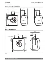
Page 23: ...01 072 2018 04 2 2 Dimensiones Modelos ES2 5 y ES4 Sólo instalación vertical Fig 5 Modelos ES8 Instalación vertical Fig 6 10 6 3 13 9 3 2 2 3 13 NPT male 13 5 3 8 1 6720801072 04 1V ES2 5 ES4 14 4 8 6720801072 06 1V 17 6 MIN OFF M AX IDEAL 17 6 1 11 4 NPT MALE 2 6 ...

Page 24: ... 8 Capacidad galones 2 7 4 0 7 0 Hor 5 1 Vert Voltaje VAC 110 120 para cada modelo Potencia a 120 VAC Watts 1440 Presión de agua máxima psi 150 Peso vacío Lbs 15 5 17 3 29 5 Intensidad de corriente Amps 12 0 para cada modelo Fases 1 Gama de temperatura F 65 145 Tasa de recuperación galones hora 6 8 Tab 2 14 4 8 17 6 17 6 6720801072 05 1V M A X MIN OFF IDEAL 3 11 4 NPT MALE 1 ...

Page 25: ...ión de la válvula de alivio de T y P Instalación vertical Si desea instalar verticalmente la unidad con las conexiones de la tubería en la parte superior Instale el tapón de latón suministrado en la llave situada en el costado del calentador de agua La válvula de alivio de temperatura y presión suministrada deberá instalarse en la parte superior En las Fig 5 y 6 puede ver la ubicación de la válvul...

Page 26: ...e Sección 504 7 3 3 Expansión térmica en un sistema cerrado Una descarga periódica de la válvula de alivio de temperatura y presión o una falla de la junta del elemento puede deberse a una expansión térmica en un sistema cerrado de suministro de agua El medidor del servicio de suministro del agua puede contener una válvula de retención obturador de contraflujo o válvula reductora de presión de agu...

Page 27: ...ircuitos u otra forma local de desconexión de todos los conductores no conectados a tierra que esté al alcance del aparato Ref NEC 422 31 Fig 8 1 Tubería de protección para cableado interno como en los modelos actuales 2 Cableado 3 Anillo de protección para cableado 4 Cable adicional de conexión a tierra AWG16 longitud mínima 152mm 5 Tapa de la caja izquierda de empalme 6 Tornillo autorroscante nº...

Page 28: ...stalado con mangueras flexibles Desconecte la fuente de alimentación Vuelque el calentador sobre un fregadero para drenar toda el agua o bien o También puede ser drenado por Extraiga el agua con sifón por la manguera del lado de la entrada Mantenga abierta una llave de agua caliente mientras extrae el agua con sifón o bien o Si el calentador ha sido instalado con tuberías rígidas Extraiga el agua ...

Page 29: ...ratamiento de agua Asegúrese siempre de que el calentador esté conectado a tierra Los modelos ES2 5 y ES4 deben estar enchufados sólo a una toma de corriente debidamente conectada a tierra La garantía del fabricante no cubre daños resultantes de la no sustitución de la barra del ánodo Si tiene preguntas adicionales llame al servicio técnico de Bosch 5 4 Desmontaje del elemento de calentamiento Des...

Page 30: ...ón 6 2 Cambio del elemento de calentamiento Desconecte la fuente de alimentación y drene el calentador consulte la sección 5 2 Drenado del calentador Retire el elemento de calentamiento consulte la sección 5 4 Desmontaje del elemento de calentamiento Instale un nuevo elemento con la junta asegurándose de que ambos estén colocados correctamente Apriete las tuercas de retención y efectúe las conexio...

Page 31: ...ta el agua compruebe si la lámpara es defectuosa Compruebe el botón de reajuste de alto límite Siga los pasos indicados en la sección 7 1 El agua sale marrón La presencia de agua marrón u oxidada indica que la barra del ánodo está gastada y un posible deterioro del cuerpo del tanque Inspeccione el tanque para ver si hay fugas de agua Compruebe la barra del ánodo véase la sección sobre el cambio de...

Page 32: ...inicio B con la punta de un bolígrafo u objeto similar Fig 13 Un clic indica que se ha activado el reinicio del sistema Vuelva a conectar el cable de alimentación IMPORTANTE Compruebe el funcionamiento del termostato Gire el selector de temperatura de alto a bajo Si no se apaga la luz roja en el ajuste bajo Desconecte la fuente de alimentación y llame a un técnico de servicio para sustituir el ter...

Page 33: ...4 443 0 ES 2 5 ES 4 ES 8 14 CAZOLETA LENTE NEON 8 738 704 446 0 ES 2 5 ES 4 ES 8 18 MANDO DE REGULACION 8 738 704 444 0 ES 2 5 ES 4 ES 8 22 VALVULA T P 8 738 704 445 0 ES 2 5 ES 4 ES 8 23 ANODO MAGNESIO D 14 L 155 M4 8 738 704 447 0 ES 2 5 ES 4 ANODO MAGNESIO D 16 L 195 8 738 704 448 0 ES 8 31 TUERCA M6 8 738 704 449 0 ES 2 5 ES 4 ES 8 33 JUNTA 4 PERNO 8 738 704 450 0 ES 2 5 ES 4 ES 8 38 LENTE NEO...

Page 34: ...instalación reparación o mantenimiento inadecuado Fallo en el mantenimiento de la barra del ánodo Consulte el Manual para la instalación y mantenimiento 2 Fallo o mal funcionamiento como resultado del suministro de agua contaminada ocorrosiva la adición de productosquímicos no autorizados el funcionamiento a temperaturas presiones o caudales anómalos o cualquier unión accesorio o componente no aut...

Page 35: ...35 Tronic 3000T 6 720 801 072 2018 04 Notas ...

Page 36: ......

Reviews: