background image

1 695 400 317

2008-10-17

Robert Bosch GmbH

32  |  TCE 5210  |   

es

Índice 

1. Símbolos 

empleados 

33

1.1 Documentación 

33

1.2 TCE 

5210 

33

2. Malfuncionamiento 

34

3. Regulaciones 

35

3.1 Verifi cación y cambio de  dirección de rotación 

de los motores eléctricos 

35

3.2 

Desbloqueo electroválvulas cetralita oleodiná-
mica 35

3.3 

Sustitución electroválvulas centralita oleodiná-
mica 35

3.4 

Regulación y sustitución correas de rotación del 
mandril 36

3.5 

Puntos de engrase 

36

3.6 

Regulación escarpias  brazo portaherramienta 37

3.7 

Sistema eléctrico trifase 

37

3.7.1 

Q1 – interruptor general 

37

3.7.2 

F1, F2, F3 – fusibles de protección del 
circuito completo de alta tensión. 

37

3.7.3 

Q3- salvamotor magnetotérmico para la 
protección del motor de la bomba hidráu-
lica 37

3.7.4 

F4 y F5 – fusibles de protección del cir-
cuito primario del transformador de ten-
sión (T 100VA) 

37

3.7.5 

F6 – fusible de protección del circuito de 
baja tensión a 24VDC 

37

3.7.6 

F7 – fusible de protección del circuito 24 
VAC 38

3.8 

Sistema eléctrico monofase 

38

3.8.1 

Q1 – interruptor general  

38

3.8.2 

F1 y F2 – fusibles de protección del cir-
cuito de alta tensión y del motor de la 
rotación del mandril. 

38

3.8.3 

Q2 – salvamotor magnetotérmico para la 
protección del motor de la bomba hidráu-
lica 38

3.8.4 

 F4 y F5 – fusibles de protección del cir-
cuito primario del transformador de ten-
sión (T 100VA) 

38

3.8.5 

F6 – fusible de protección del circuito de 
baja tensión a 24VDC 

39

3.8.6 

F7 – fusible de protección del circuito 24 
VAC 39

3.9 

Sustitución joystick pedalera comando 

41

3.10  Sustitución cable pedalera comando y pedalera 

completa 41

3.11  Sustitución del micro de rotación del mandril de 

la pedalera comando 

42

3.12  Sustitución muelle balanceador de rotación man-

dril pedalera comando 

43

3.13  Sustitución de los patines del carro del brazo de 

la herramienta 

44

4. 

Tabla comparativa aceites hidraúlicos 

45

4.1 

Control nivel de aceite 

45

Summary of Contents for TCE 5210

Page 1: ...TCE 5210 en Repair instructions Tyre changer de Instandsetzungsanleitung Tyre changer es Instructions de réparation Tyre changer it Istruzioni di riparazione Tyre changer ...

Page 2: ...1 695 400 317 2008 10 17 Robert Bosch GmbH 2 TCE 5210 ...

Page 3: ...1 695 400 317 2008 10 17 Robert Bosch GmbH TCE 5210 3 Inhaltsverzeichnis Deutsch 4 Contents English 18 Índice Español 32 Indice Italiano 46 ...

Page 4: ...spannungsschaltkreises mit 24VDC 9 3 7 6 F7 Sicherung zum Schutz des Schalt kreises mit 24VAC 10 3 8 Elektrische Einphasenanlage 10 3 8 1 Q1 Hauptschalter 10 3 8 2 F1 und F2 Sicherungen zum Schutz des Hochspannungsschaltkreises sowie des Motors für die Drehbewegung der Spann futterwelle 10 3 8 3 Q2 Magnetothermischer Motorschutz schalter für den Schutz des Motors der Hydraulikpumpe 11 3 8 4 F4 und...

Page 5: ... Körperverletzungen oder zu größe ren Sachschäden führen könnte Achtung warnt vor möglicherweise schädlichen Situationen bei der TCE 5210 der Prüfling oder eine Sache in der Umgebung beschädigt werden könnte Zusätzlich zu den Warnhinweisen werden folgende Sym bole verwendet Info i Anwendungshinweise und andere nützliche Informationen Einschrittige Handlungsaufforderung nur aus ei nem Schritt beste...

Page 6: ...r Pedal Einheit beschädigt austauschen Das selbstzentrierende Spannfutter dreht mit zu geringer Antriebskraft Sicherstellen dass die Netzspannung und die auf dem Maschinenkennschild angegebene Ver sorgungsspannung übereinstimmen Den Riemenspanner nachspannen siehe Anleitungen Die Sicherungen prüfen Das selbstzentrierende Spannfut ter spannt das Rad nicht korrekt ein Sicherstellen dass sich der Mot...

Page 7: ...einem Einphasenmotor sind die elektrischen 5 Schaltpläne zu berücksichtigen das Klemmengehäuse auf dem Motor wieder schlie 6 ßen die Übereinstimmung der Drehrichtung mit dem auf 7 den Motor aufgeklebten Pfeil und der Abbildung überprüfen Manuelle Entsperrung der Magnet 3 2 ventile des Hydraulik Steuergeräts Falls eine oder mehrere Hydraulikbewegungen nicht durchgeführt werden und eine elektrische ...

Page 8: ...n die Stromversorgung an 10 schließen und ihre korrekte Betriebsweise überprü fen Einstellung und Austausch des An 3 4 triebsriemens der Spannfutterwelle Einstellung der Riemenspannung Die Maschine von der Stromversorgung trennen 1 die Schutzabdeckung der Riemen entfernen 2 von Hand die Riemenspannung prüfen bei einem zu 3 lockeren Riemen ist wie folgt vorzugehen die Kontermutter auf dem Motor loc...

Page 9: ...s Reifenmon tiergerät stets von der Stromversorgung getrennt werden Beschreibung der Komponenten und ihrer Funktion Q1 Hauptschalter 3 7 1 Unter normalen Betriebsbedingungen muss dieser Schalter in der Position 1 auf ON stehen Diese Vor richtung trennt die gesamte elektrische Anlage von der Spannungsquelle F1 F2 F3 Sicherungen zum Schutz des 3 7 2 gesamten Hochspannungsschaltkreises Sie gestatten ...

Page 10: ...abel der Pedal Einheit nicht beschä digt ist und dass die Kabel im Innern nicht durchgetrennt sind oder ein Kurzschluss an den Kabeln vorliegt bzw dass die Mikroschalter der Pedal Einheit nicht beschädigt sind was ebenfalls zu einem Kurzschluss führen kann Anschließend sind auch die beiden Fernschalter für die Drehbewegung der Spannfutterwelle insbesondere die Spulen zu überprüfen Elektrische Einp...

Page 11: ...ulikpumpe F6 Sicherung zum Schutz des Niederspannungsschaltkreises mit 24VDC 3 8 5 Wenn diese Sicherung ausgelöst wird funktioniert keine der hydraulisch gesteuerten Bewegungen mehr wohinge gen die übrigen Bewegungen wie z B die Drehbewegung der Spannfutterwelle noch funktionieren Überprüfen dass das Verbindungskabel der Pedal Einheit nicht beschädigt ist und dass die Kabel im Innern nicht durchge...

Page 12: ...otoren gearbeitet wird da diese für lange Zeit eine elektrische Restladung aufweisen und daher die Gefahr von starken Stromschlägen besteht wenn die Kondensatoren versehentlich berührt werden Sollte die Wiederherstellung des elektrischen Anschlusses des Motors für die Drehung der Spannfutterwelle erfor derlich sein wird auf den unten dargestellten elektrischen Schaltplan verwiesen ...

Page 13: ...rung einbauen und die bei 5 den Feststellschrauben anziehen die zuvor abge klemmten Kabel wieder anschließen und dabei die angebrachten Markierungen berücksichtigen anschließend die vier Schrauben der vorderen Ab 6 deckung der Pedal Einheit wieder anziehen Austausch des Kabels bzw der ge 3 10 samten Pedal Einheit Infolge einer intensiven langen Nutzung des Geräts kann der Austausch des Verbindungs...

Page 14: ...el lösen nachdem alle Kabel abgeklemmt wurden die alte 4 Pedalsteuerung ausbauen und das Kabel der neuen Pedalsteuerung in die elektrische Schalttafel füh ren die Kabel der neuen Pedalsteuerung an das Klem 5 menbrett im elektrischen Schaltkasten anschließen und dabei in umgekehrter Reihenfolge wie zuvor vorgehen vor dem Wiedereinbau sämtlicher Abdek kungen daran denken die betreffenden Bewegun gen...

Page 15: ...n das Pedal für die Drehbewegung der Spannfutter welle nach unten gedrückt bleibt und nicht in die Aus gangsposition zurückkehrt muss die Pedalfeder für die Drehbewegung des Spannfutters Uhrzeigersinn gegen den Uhrzeigersinn ausgewechselt werden Das Reifenmontiergerät von der Stromversorgung 1 trennen die Abdeckung im unteren Bereich der Pedalsteue 2 rung mit einem Schraubenzieher öffnen nun ist d...

Page 16: ...muss darauf ge achtet werden dass die Kunststoffführungen immer paarweise entfernt werden insbesondere das zweite Paar Nun einen Rollenzug eine Hubvorrichtung einen Gabelstapler oder alternativ dazu 3 4 Bediener bereitstellen denn nach dem kompletten Ausbau ist der Schlitten vollkommen halterlos und wird nicht mehr durch die Führungen abgestützt Damit die Handhabung des Schlittens einfacher 4 wird...

Page 17: ...auch die Kontermuttern endgültig anziehen Sämtliche zuvor abgenommene Schutzabdeckun 13 gen wieder montieren Vergleichende Tabelle der 4 Hydrauliköle Falls im Zuge von Reparatureingriffen bei Ölaustritten Austausch von Komponenten etc das Nachfüllen von Hydrauliköl zur Wiederherstellung des erforderlichen Ölstandes notwendig sein sollte sind die Produkthin weise der nachfolgenden Tabelle zu berück...

Page 18: ...A 23 3 7 5 F6 protection fuse of the low tension 24VDC circuit 23 3 7 6 F7 protection fuse of the 24VAC circuit24 3 8 Single phase electrical system 24 3 8 1 Q1 main switch 24 3 8 2 F1 and F2 protection fuses of the high tension circuit and of the mandrel rota tion motor 24 3 8 3 Q2 thermal magnetic motor protector for the protection of the hydraulic pump motor 24 3 8 4 F4 and F5 protection fuses ...

Page 19: ...damage to property Important warns of a potentially hazardous situati on in which the TCE 5210 the test sample or other object in the vicinity could be damaged In addition to these warnings the following symbols are also used Info i In addition to these warnings the following symbols are also used Single step procedure instructions for a procedure that can be completed in just one step Intermediat...

Page 20: ...ox defective replace Pedal box cable damaged replace The self centering chuck turns with insufficient strength Check the correspondence of the mains tension with that shown on the registration plate Adjust the belt tightener see instructions Check the fuses The self centering chuck does not lock the wheel correctly Check that the motor of the control pa nel turns in the correct direction Check the...

Page 21: ...ase of one phase motor proceed as indicated in 5 the electrical diagrams Close the terminal board box on the motor 6 Check the rotation direction by means of the arrow 7 sticker on the motor itself and shown in the picture Hydraulic panel electrovalve release 3 2 In case one or more hydraulic motions are not executed and it is clear that this is not caused by an electrical problem you can proceed ...

Page 22: ...ent Disconnect the machine from power supply 1 Remove the belts protection cover 2 Test manually belts tension if too loose operate as 3 follows Loosen the counter nut on the motor Operate on the screw itself in order to restore the correct tension Tighten with the counter nut Belts replacement Disconnect the machine from power supply 1 Remove the belts protection cover 2 Loosen the counter nut on...

Page 23: ... ON This device powers up or off the entire electrical circuit F1 F2 F3 protection fuses of the whole 3 7 2 high tension circuit Allow power supply to the main circuit of the tension transformer and to the motor of the rotation mandrel Q3 thermal magnetic motor protector for the 3 7 3 protection of the motor and of the hydraulic pump If activated check the connections of the motor its energy absor...

Page 24: ...tension circuit and of the mandrel rotation motor 3 8 2 In case it is necessary to reverse the rotation direction of the motor follow the attached connection diagram Q2 thermal magnetic motor protector for the protection of the hydraulic pump motor 3 8 3 If activated check the connections of the motor its energy absorption and the correct calibration of the device according to the characteristics ...

Page 25: ...l box is not damaged and that the cables inside are not interrupted or short circuited and that the micro switches on the pedal box are not short circuited if they are damaged Finally check also the two remote control switches of the rotation mandrel specially the coils With this type of single phase machinery be very careful when operating on the motor condensers since they retain for a long time...

Page 26: ...695 400 317 2008 10 17 Robert Bosch GmbH 26 TCE 5210 Adjustments en If need be in order to restore the electrical connection of the motor of the rotation mandrel follow the electrical diagram shown below ...

Page 27: ...ock 5 screws reconnect the wires previously disconnected according to the connections that have been noted before Finally close the four screws of the front panel on 6 the pedal box Replacement of the pedal box cable 3 10 and of the entire pedal box After a period of hard work the replacement of the ca ble that connects the electrical panel and the pedal box might be necessary sometimes the entire...

Page 28: ...x they can be identified follow ing the group of wires that go from the pedal box to the electrical panel In order to do that insert in the terminal board box 3 a screw driver of suitable dimensions until you hear a click that releases the wire from the terminal board box After having disconnected all cables remove the old 4 pedal box and insert the cable of the new one in the electrical panel Rec...

Page 29: ...ttom of the pedal box with the four screws in reversed order to what previously done to open the pedal box Replacement of the spring of the 3 12 rocker arm of the control pedal box rotation mandrel In case the pedal of the rotation mandrel remains still in a lower position and does not return back in order to replace the spring of the rocker arm of the rotation mandrel clockwise counter clockwise ...

Page 30: ...h out completely the trolley from the right 3 side being careful to let out a pair of sliders at a time specially the second pair be ready with a tackle or a lifter or a forklift or as an alternative 3 4 operators because when completely out the trolley will be completely released and without support of the guides In case you want to be more comfortable when han 4 dling the trolley it is possible ...

Page 31: ...with the 12 key give another turn and tighten also definitively the counter nuts Reassemble all coverings and metal sheets previ 13 ously disassembled Hydraulic oils comparison 4 table In the event that after some repairs oil losses replace ments of items or other it is necessary to restore the correct level of any oil type follow what is reported in the table below Type Model Standards Gearbox oi...

Page 32: ...00VA 37 3 7 5 F6 fusible de protección del circuito de baja tensión a 24VDC 37 3 7 6 F7 fusible de protección del circuito 24 VAC 38 3 8 Sistema eléctrico monofase 38 3 8 1 Q1 interruptor general 38 3 8 2 F1 y F2 fusibles de protección del cir cuito de alta tensión y del motor de la rotación del mandril 38 3 8 3 Q2 salvamotor magnetotérmico para la protección del motor de la bomba hidráu lica 38 3...

Page 33: ... de carácter leve o importantes daños materiales Atención Advierte de situaciones potencialmente perjudiciales en las cuales se podría perjudicar el TCE 5210 la probeta o algún objeto del entorno Además de las indicaciones de aviso se utilizan los siguientes símbolos Información i Indicaciones para la aplicación y otras informaciones útiles Instrucción de actuación paso a paso Instrucción de actua...

Page 34: ...o en pedalera defectuoso sustituir Cable de la pedalera dañado sustituir El autocentrante gira con fuerza insuficiente Verificar la correspondencia entre la tensión de red y aquella indicada en la tarjeta del constructor Accionar el tensor de correa ver instrucciones Controlar los fusibles El autocentrante no bloquea la rueda correctamente Asegurarse que el motor de la centralita gi re en el senti...

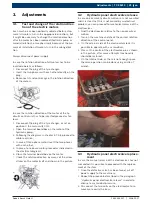
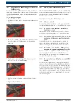
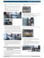
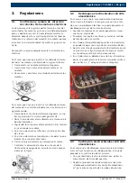
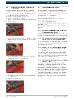
Page 35: ...ores monofásicos respetar lo que 5 indican los esquemas eléctricos Cerrar la caja de morsetería ubicada en el motor 6 Controlar la dirección de rotación a través de la 7 flecha adhesiva pegada en el motor mismo como se indica en la figura Desbloqueo electroválvulas cetralita 3 2 oleodinámica En el caso en que uno ó más movimientos hidráulicos no se hayan efectuado y se asegure que no tiene rela ci...

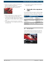
Page 36: ...e la tensión de las correas Desconectar la máquina de la alimentación eléctrica 1 Remover el carter de protección de las correas 2 Testear manualmente la tensión de las correas si es 3 tán demasiado flojas realizarlo del siguiente modo Aflojar la contratuerca presente en el motor Accionar el tornillo mismo para retomar la tensión adecuada Cerrar con la contatuerca Sustitución de las correas Descon...

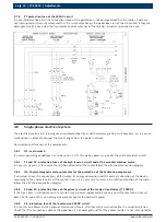
Page 37: ...r ubicado en 1 ON Este dispositivo da ó quita tensión al circuito eléctrico completo F1 F2 F3 fusibles de protección del circui 3 7 2 to completo de alta tensión Permiten la alimentación del circuito primario del trans formador de tensión y motor de la rotación del mandril Q3 salvamotor magnetotérmico para la pro 3 7 3 tección del motor de la bomba hidráulica Si salta verificar las conexiones del ...

Page 38: ...mas de la red eléctrica Descripción de los componentes y sus funciones Q1 interruptor general 3 8 1 En condiciones de normal funcionamiento debe estar ubicado en 1 ON Este dispositivo da ó quita tensión al circuito eléctrico completo F1 y F2 fusibles de protección del circuito de alta tensión y del motor de la rotación del mandril 3 8 2 En caso que sea necesario invertir el sentido de rotación del...

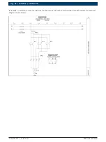
Page 39: ...tromgnéticas de las electroválvulas o los microin terruptores de la pedalera que pueden estar en cortocircuito si se dañan esto ocurre raramente pero es posible F7 fusible de protección del circuito 24 VAC 3 8 6 En el caso que salte verificar que el cable de conexión de la pedalera no esté dañado y que los cables en el interi or no estén interrumpidos o en cortocircuito que los microinterruptores ...

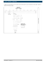
Page 40: ... 400 317 2008 10 17 Robert Bosch GmbH 40 TCE 5210 Regulaciones es Si hubiese necesidad de retomar la conexión eléctrica del motor de la rotación eléctrica del mandril respetar el esquema eléctrico que sigue ...

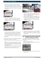
Page 41: ...r los dos tornillos 5 de bloqueo reconectando los cables antes descon ectados respetando las conexiones anteriormente apuntadas Al final cerrar los cuatro tornillos del panel frontal de 6 la pedalera Sustitución cable pedalera comando 3 10 y pedalera completa Después de un período de intenso trabajo puede ser necesaria la sustitución del cable de conexión entre el cuadro eléctrico y la pedalera co...

Page 42: ...léctrico van a la pedalera localizables siguiendo el grupo de cables que llega desde la pedalera dentro del cuadro eléctrico Para realizar eso insertar en la morsetería un destor 3 nillador de dimensiones adecuadas hasta sentir un golpecito que hará el cable de la morsetería Después de haber desconectado todos los cables 4 quitar la vieja pedalera e insertar el cable de la nueva en el cuadro eléct...

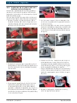
Page 43: ... pedalera comando En el caso que el pedal de la rotación del mandril que de fijo en una posición hacia abajo y no vuelva para sustituir el muelle balanceador de la rotación del man dril horario antihorario realizarlo según las siguientes instrucciones Quitar tensión a la máquina 1 Abrir la parte baja de la pedalera con la ayuda de un 2 destornillador Ahora se puede acceder al muelle del balanceado...

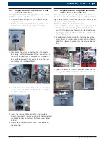
Page 44: ...ara hacer sa lir una pareja de patines a la vez sobre todo los segundos acompañar la operación con una grúa o levantador ó como alternativa 3 4 operarios porque cuando el carro salga completamente quedará libre y sin el sustento de las guías En el caso que se quiera estar más cómodos al mo 4 ver el carro se puede quitar el grupo de herramien tas del carro mismo Con el carro ubicado en el suelo mon...

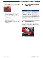
Page 45: ...ar todo el carter y las láminas desmontadas 13 anteriormente Tabla comparativa aceites 4 hidraúlicos Si después de las reparaciones pérdidas de aceite su stitución de partes etc existe la necesidad de resete ar el correcto nivel de cualquier tipo de aceite respetar lo que indica la siguiente tabla Tipo Modelo Normas Aceite para re ductores Esso Spar tan EP 460 ISO 460 DIN 51502 CLP ISO 34 98 CC Ac...

Page 46: ...T 100VA 51 3 7 5 F6 fusibile di protezione del circuito di bassa tensione a 24VDC 51 3 7 6 F7 fusibile di protezione del circuito 24VAC 52 3 8 Impianto elettrico monofase 52 3 8 1 Q1 interruttore generale 52 3 8 2 F1 e F2 fusibili di protezione del circuito alta tensione e al motore della rotazione mandrino 52 3 8 3 Q2 salvamotore magnetotermico per la protezione del motore della pompa idrau lica ...

Page 47: ...uò comportare lievi lesioni fisiche o gravi danni materiali Attenzione segnala situazioni potenzialmente pericolose che possono danneggiare il TCE 5210 il campione o un bene nell ambiente Oltre alle indicazioni di avvertimento vengono impiega ti i seguenti simboli Info i indicazioni applicative ed altre informazioni utili Istruzioni rapide istruzioni costituite solo da una fase Risultato intermedi...

Page 48: ...iera difettoso sostituire Cavo della pedaliera danneggiato sostituire L autocentrante gira con forza insufficiente Verificare la corrispondenza fra la tensione di rete e quella indicata sulla targhetta del costruttore Agire sul tendicinghia vedi istruzioni Controllare i fusibili L autocentrante non blocca correttamente la ruota Assicurarsi che il motore della centralina gi ri nel senso di rotazion...

Page 49: ... dagli schemi elettrici Richiudere la scatola morsettiera posta sul motore 6 Controllare in verso di rotazione tramite la freccia 7 adesiva posta sul motore stesso e indicato in figura Sblocco elettrovalvole centralina 3 2 oleodinamica Nel caso uno o più di un movimento idraulico non siano effettuati e si sia appurato che non dipende da un pro blema elettrico si può procedere allo sblocco manuale ...

Page 50: ...entazione elettrica 1 Rimuovere il carter di protezione delle cinghie 2 Testare manualmente la tensione delle cinghie se 3 troppo lenta operare come segue Allentare il controdado presente sul motore Agire sulla vite stessa per ripristinare la giusta tensione Serrare con il contro dado Sostituzione delle cinghie Scollegare la macchina dall alimentazione elettrica 1 Rimuovere il carter di protezione...

Page 51: ...tivo da o toglie ten sione all intero circuito elettrico F1 F2 F3 fusibili di protezione dell intero 3 7 2 circuito alta tensione Consentono l alimentazione al circuito primario del trasformatore di tensione e al motore della rotazione mandrino Q3 salvamotore magnetotermico per la pro 3 7 3 tezione del motore della pompa idraulica Se scatta verificare i collegamenti del motore l assorbimento dello...

Page 52: ... funzionamento deve essere posizionato su 1 ON Questo dispositivo da o toglie tensio ne all intero circuito elettrico F1 e F2 fusibili di protezione del circuito alta tensione e al motore della rotazione mandrino 3 8 2 Nel caso sia necessario invertire il senso di rotazione del motore seguire lo schema di collegamento allegato Q2 salvamotore magnetotermico per la protezione del motore della pompa ...

Page 53: ...era che possono andare in corto circuito se si danneggiano F7 fusibile di protezione del circuito 24VAC 3 8 6 Nel caso salti verificare quindi il cavo di collegamento della pedaliera che non sia danneggiato e che i cavi all interno non siano interrotti o in corto circuito che i micro interruttori sulla pedaliera non siano in corto circuito se si danneggiano Infine verificare anche i due teleruttor...

Page 54: ...2008 10 17 Robert Bosch GmbH 54 TCE 5210 Regolazioni it Qualora ve ne fosse la necessità per ripristinare il collegamento elettrico del motore della rotazione mandrino attenersi allo schema elettrico sotto riportato ...

Page 55: ...ima Infine richiudere le quattro viti del pannello frontale 6 sulla pedaliera Sostituzione cavo pedaliera comando 3 10 e pedaliera completa Dopo un periodo di intenso lavoro può rendersi ne cessaria la sostituzione del cavo di collegamento tra il quadro elettrico e la pedaliera comando se non a volte della pedaliera comando completa Nel caso seguire le indicazioni fornite di seguito Togliere tensi...

Page 56: ...tti i cavi rimuovere la vec 4 chia pedaliera ed inserire il cavo della nuova nel quadro elettrico Ricollegare i cavi della nuova pedaliera nella 5 morsettiera del quadro elettrico eseguendo l operazione inversa descritta precedentemente avendo cura di controllare l esattezza dei movimen ti prima di richiudere il tutto Se tutto funziona correttamente richiudere anche 6 il quadro elettrico dare tens...

Page 57: ...2 cacciavite Ora c è la possibilità di accedere alla molla del bilan 3 ciere e procedere con la sua sostituzione Rimuovere la spina di bloccaggio con idonea attrez 4 zatura se propriamente rimossa può essere riutiliz zata Estrarre il bilanciere dalla parte esterna tirandolo 5 Rimuovere la molla danneggiata inserire la nuova 6 ingrassandola abbondantemente ed inserire nuova mente il bilanciere nel ...

Page 58: ...ò il più possibile le viti di registro Anche in questo caso attrezzarsi con un paranco o 6 sollevatore o muletto o in alternativa 3 4 operatori perché essendo completamente fuori il carrello sarà completamente libero e senza il sostegno delle gui de puntare solo leggermente i bulloni di registro Lubrificare abbondantemente tutte le guide di scor 7 rimento inserire la prima coppia di pattini e semp...

Page 59: ...ersi a quanto riportato nella tabella sotto stante Tipo Modello Norme Olio per riduttore Esso Spar tan EP 460 ISO 460 DIN 51502 CLP ISO 34 98 CC Olio per pompa Idraulica Esso Nuto H46 ISO 46 DIN 51502 HLP DIN 51524 PART 2 HLP ISO 67 43 HM Olio lubrifican te per sistema pneumatico Esso Febis K32 ISO 32 Controllo livello olio 4 1 Per fare ciò togliere tensione all attrezzatura e svitare il tappo con...

Page 60: ...Robert Bosch GmbH Diagnostics Franz Oechsle Straße 4 73207 Plochingen DEUTSCHLAND www bosch com bosch prueftechnik bosch com Printed in Germany Imprimé en Allemagne 1 695 400 317 2008 10 17 ...

Reviews: