background image

Connection Technique

8.1 

Variants

MKE motors are available in:

Housing type E (according to European standard EN)

Housing type U (according to American Standard UL)

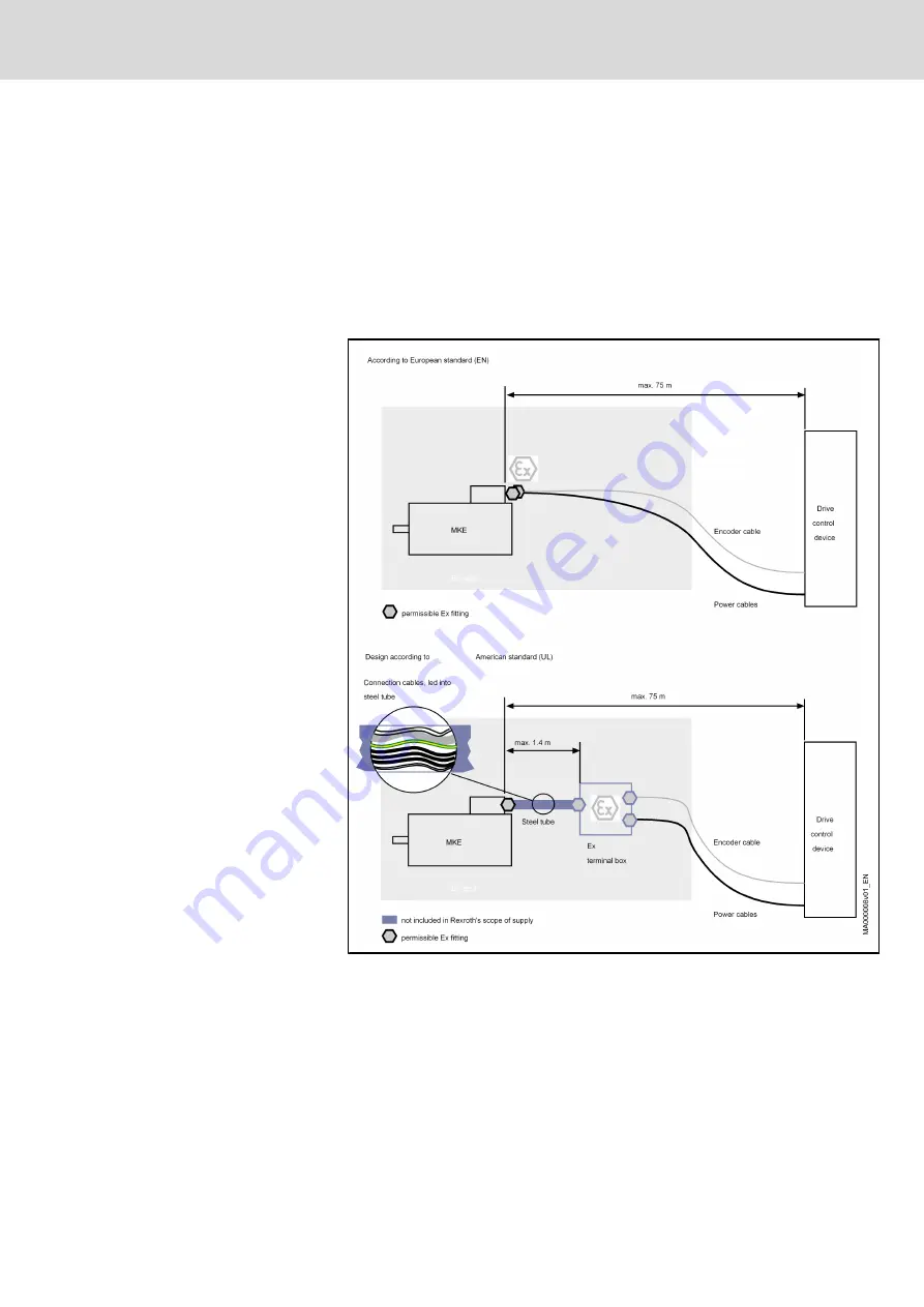
The different regulations of the responsible public authority require the con‐

nection variants shown below.

Fig.8-1:

Connection variants MKE motors

Thermostat connection

If MKE motors are used in potentially explosive areas, the analysis of the motor

temperature has to be done at Rexroth by means of the drive control device

IndraDrive

DuraDrive

EcoDrive

DIAX04

offered by Rexroth.

Project Planning Manual | Rexroth MKE Synchronous Motors

 Electric Drives

and Controls

| Bosch Rexroth AG

65/131

Connection Technique

Summary of Contents for Rexroth MKE Series

Page 1: ...ronous Motors for Potentially Explosive Areas according to ATEX and UL CSA R911297663 Edition 04 Electric Drives and Controls Pneumatics Service Linear Motion and Assembly Technologies Hydraulics Project Planning Manual ...

Page 2: ... case of contravention All rights are reserved in the event of the granting of a patent or the registration of a utility model or design DIN 34 1 Legal validity The data listed in this document only describe the product they must not be understood as guaranteed properties in the legal sense We reserve the right to modify the contents of this documentation and the availability of the products Publi...

Page 3: ... weitergegeben werden Bewahren Sie diese Anleitung auf English This documentation must be kept by the user during the whole pe riod of use and lifetime of the product and be passed on in case of sale Save these instructions Project Planning Manual Rexroth MKE Synchronous Motors Electric Drives and Controls Bosch Rexroth AG I VI ...

Page 4: ...II VI Bosch Rexroth AG Electric Drives and Controls Rexroth MKE Synchronous Motors Project Planning Manual ...

Page 5: ... of Safety Symbols and Hazard Classification 16 3 3 Instructions with Regard to Specific Dangers 16 3 3 1 Protection Against Contact with Electrical Parts and Housings 16 3 3 2 Protective Extra Low Voltage as Protection Against Electric Shock 17 3 3 3 Protection Against Dangerous Movements 18 3 3 4 Protection Against Magnetic and Electromagnetic Fields During Operation and Mounting 20 3 3 5 Protec...

Page 6: ...ions 69 9 Operating Conditions and Application Notes 73 9 1 Potentially Explosive Areas 73 9 1 1 Terms and Definitions 73 General 73 The following terms are used in the European Standard EN 50014 1992 74 Zones 76 Degree of ignition protection groups and temperature classes 76 9 1 2 Application Conditions for MKE Motors 77 General 77 Motor internal holding brake if applicable 78 9 1 3 Type Test of ...

Page 7: ...EU Version 93 9 12 2 Motors in UL Version 93 10 State of Delivery Identification Handling Transport and Storage 95 10 1 State of Delivery 95 10 1 1 Packaging 95 10 1 2 High voltage Test 95 10 2 Identification 95 10 2 1 Shipping Documents and Delivery Note 95 10 2 2 Name Plate 95 10 3 Handling Transport and Storage 96 11 Installation 99 11 1 Safety 99 11 2 Skilled Personnel 99 11 3 Mechanical Mount...

Page 8: ...ted Substances 117 13 1 3 No Release of Hazardous Substances 117 13 1 4 Principal Components 117 13 2 Disposal 117 13 2 1 Return of Products 117 13 2 2 Packaging Materials 117 13 2 3 Recycling 118 14 Appendix 119 14 1 List of Standards 119 14 2 Selection of Connection Cable 121 14 2 1 Power Cable IndraDyn S MKE 121 14 2 2 Encoder Cable IndraDyn S MKE 122 14 3 Declaration of Conformity 123 15 Servi...

Page 9: ...lowing power spectrum Fig 1 1 MKE power gradation Performance features MKE motors are characterized by the following advantages Motor construction in Flameproof Enclosures according to EN 50 014 1992 High operational reliability Maintenance free operation owing to the brushless design and use of bearings grease lubricated for their entire lifetime Use under adverse environmental conditions is poss...

Page 10: ...ent magnet motors with electronic commutation Spe cial magnet materials permit the motors to be designed with low inertia masses The following figure shows the principal design of MKD motors 1 Drive shaft 2 Stator with winding 3 Bearings 4 Motor encoder 5 Connection unit 6 Terminal box lid 7 Holding brake optional 8 Grounding clamp 9 Shaft sealing ring 10 Rotor with permanent magnets Fig 1 2 Desig...

Page 11: ...e of delivery identification handling transport and storage Practical information for op erating and maintenance personnel 11 Installation 12 Startup operation and maintenance 13 Environmental protection and disposal General information 14 Appendix 15 Service and support Index Fig 1 3 Document structure 1 2 2 Additional Documentation If this documentation contains references to additional documen ...

Page 12: ... 2 5 Your Feedback Your experiences are an essential part of the process of improving both the product and the documentation Please do not hesitate to inform us of any mistakes you detect in this docu mentation or of any modifications you might desire We would appreciate your feedback Please send your remarks to Bosch Rexroth AG Dep BRC EDM2 Buergermeister Dr Nebel Strasse 2 97816 Lohr Germany Fax...

Page 13: ...erstand the corresponding notes regarding safety and regarding the intended use If the products are hardware they must be kept in their original state i e no constructional modifications must be made Software products must not be decompiled their source codes must not be modified Damaged or improperly working products must not be installed or put into operation It must be ensured that the products...

Page 14: ...tection humidity EMC and the like specified in this documentation 2 2 Inappropriate Use Any use of MKE motors outside of the fields of application mentioned above or under operating conditions and technical data other than those specified in this documentation is considered to be inappropriate use MKE must not be used if the ambient conditions require a higher explosion protection than is indi cat...

Page 15: ...as a single functional unit Machine Entirety of interconnected parts or units at least one of which is movable Thus a machine consists of the appropriate machine drive elements as well as con trol and power circuits which have been assembled for a specific application A machine is for example intended for processing treatment movement or packaging of a material The term machine also covers a combi...

Page 16: ...ore initial commissioning of the electric com ponents of the drive and control system in order to eliminate the risk of injury and or property damage You must follow these safety instructions Bosch Rexroth is not liable for damages resulting from failure to observe the safety instructions Read the operating maintenance and safety instructions in your language before commissioning If you find that ...

Page 17: ...allation manufacturer is responsible for compliance with the limit values as prescribed in the national regulations The technical data connection and installation conditions of the compo nents are specified in the respective application documentations and must be followed at all times National regulations which the user must take into account European countries According to European EN standards U...

Page 18: ...or serious injury could occur Caution Minor or moderate injury or property damage may oc cur Fig 3 1 Hazard classification according to ANSI Z535 4 2002 3 3 Instructions with Regard to Specific Dangers 3 3 1 Protection Against Contact with Electrical Parts and Housings This section concerns components of the drive and control system with voltages of more than 50 volts Contact with parts conducting...

Page 19: ...omponent has been pow ered As a basic principle residual current operated circuit breakers cannot be used for electric drives to prevent direct contact Secure built in devices from penetrating foreign objects and water as well as from direct contact by providing an external housing for example a control cabinet WARNING High housing voltage and high leakage current Danger to life risk of injury by ...

Page 20: ... before commissioning Malfunction of sensors and encoders Defective components Software or firmware errors These errors can occur immediately after equipment is switched on or even after an unspecified time of trouble free operation The monitoring functions in the components of the drive and control system will normally be sufficient to avoid malfunction in the connected drives Regarding personal ...

Page 21: ...of an emergency stop circuit or use a safe starting lockout Make sure that the drives are brought to a safe standstill before accessing or entering the danger zone Additionally secure vertical axes against falling or dropping after switching off the motor power by for example mechanically securing the vertical axes adding an external braking arrester clamping mechanism or ensuring sufficient equil...

Page 22: ... CAUTION Hot surfaces of components of the drive and control system Risk of burns Do not touch hot surfaces of for example braking resistors heat sinks supply units and drive controllers motors windings and laminated cores According to the operating conditions temperatures of the surfaces can be higher than 60 C 140 F during or after operation Before touching motors after having switched them off ...

Page 23: ...teries as this may cause leakage or explosion Do not throw batteries into open flames Do not dismantle batteries When replacing the battery batteries do not damage the electrical parts installed in the devices Only use the battery types specified for the product Environmental protection and disposal The batteries contained in the product are considered dangerous goods during land air and sea trans...

Page 24: ...oes safety gloves for example Immediately clean up any spilled liquids from the floor due to the risk of slipping Environmental protection and disposal The agents e g fluids used to operate the product might not be environmentally friendly Dispose of agents harmful to the environment separately from other waste Observe the national regulations of your country 22 131 Bosch Rexroth AG Electric Drive...

Page 25: ...ot mean square value of the induced motor voltage at a motor temperature of 20 C and 1000 revolutions per minute Winding resistance at 20 C R12 Ohm Resistance measured between two winding ends in ohms Ω Winding inductivity L12 mH Inductivity measured between two phases in mH Discharge capacity Cab Number of pole pairs o Moment of inerta of rotor1 Jrot kgm2 Moment of inertia of the rotor without th...

Page 26: ...ding brake Fig 4 2 Data sheet Description of individual values 4 1 2 Parameters of the Characteristic Curves The speed torque curves and the technical data are specified in consideration of the following conditions When selecting the technical data observe the temperatures speci fied The motor data and characteristic curves are determined using MKE motors under the following conditions Ambient tem...

Page 27: ...n of the ON time ED in The operating time is calculated as follows ED Cyclic duration factor in ΔtP Operating time with constant load Fig 4 4 Cyclic duration factor The values specified in the documentation have been determined on the basis of the following parameters Cycle duration 15 min Operating time ED 25 If valid conditions deviating therefrom are marked accordingly Project Planning Manual R...

Page 28: ...15 0 Maximum speed nmax min 1 9000 Sound pressure level LP dB A 75 Weight 2 m kg 2 5 2 8 Ambient temperature in operation Tam C 0 40 Degree of protection IP 65 Insulation class according to DIN EN 60034 1 F Holding brake optional Holding torque M4 Nm 1 0 Rated voltage 10 UN V 24 0 Rated current IN A 0 4 Connection time t1 ms 3 Disconnection time t2 ms 4 Moment of inertia of brake JBr kgm2 0 000007...

Page 29: ...earing load For additional information about permissible radial and axial forces see the chapter chapter 9 10 Bearings and Shaft Load on page 86 Diagram for determining the maximum permissible radial Fradial Fig 4 7 MKE037 permissible radial force shaft and bearing load Axial force not permissible Project Planning Manual Rexroth MKE Synchronous Motors Electric Drives and Controls Bosch Rexroth AG ...

Page 30: ...0 Maximum speed nmax min 1 7000 Sound pressure level LP dB A 75 Weight 2 m kg 5 5 5 8 Ambient temperature in operation Tam C 0 40 Degree of protection IP 65 Insulation class according to DIN EN 60034 1 F Holding brake optional Holding torque M4 Nm 2 2 Rated voltage 10 UN V 24 Rated current IN A 0 34 Connection time t1 ms 2 8 Disconnection time t2 ms 14 Moment of inertia of brake JBr kgm2 0 00001 1...

Page 31: ... 144 Bearing and shaft load For additional information about permissible radial and axial forces see chapter 9 10 Bearings and Shaft Load on page 86 Diagram for determining the maximum permissible radial Fradial Fig 4 10 MKE047 permissible radial force shaft and bearing load Permissible axial force 30 Nm Project Planning Manual Rexroth MKE Synchronous Motors Electric Drives and Controls Bosch Rexr...

Page 32: ...h min 60 0 Maximum speed nmax min 1 4500 5000 Weight 2 m kg 18 0 19 1 Sound pressure level LP dB A 75 Ambient temperature in operation Tam C 0 40 Degree of protection IP 65 Insulation class according to DIN EN 60034 1 F Holding brake optional Holding torque M4 Nm 11 0 Rated voltage 10 UN V 24 0 Rated current IN A 0 71 Connection time t1 ms 30 Disconnection time t2 ms 11 Moment of inertia of brake ...

Page 33: ...ntrolled feed 3 x AC 480V Mmax IndraDrive uncontrolled feed 3 x AC 440V Mmax IndraDrive uncontrolled feed 3 x AC 400V Fig 4 13 Motor s characteristic curve MKE098B 058 Bearing and shaft load For additional information about permissible radial and axial forces see chapter 9 10 Bearings and Shaft Load on page 86 Diagram for determining the maximum permissible radial Fradial Project Planning Manual R...

Page 34: ...4 MKE098 permissible radial force shaft and bearing load Permissible axial force 60 Nm 32 131 Bosch Rexroth AG Electric Drives and Controls Rexroth MKE Synchronous Motors Project Planning Manual Technical Data ...

Page 35: ...t Tth min 90 0 Maximum speed nmax min 1 4000 4500 Sound pressure level LP dB A 75 Weight 2 m kg 44 45 1 Ambient temperature in operation Tam C 0 40 Degree of protection IP 65 Insulation class according to DIN EN 60034 1 F Holding brake optional Holding torque M4 Nm 22 0 Rated voltage 10 UN V 24 0 Rated current IN A 0 71 Connection time t1 ms 25 Disconnection time t2 ms 15 Moment of inertia of brak...

Page 36: ...otor s characteristic curve MKE118B 024 Mmax IndraDrive controlled feed 3 x AC 400V Mmax IndraDrive uncontrolled feed 3 x AC 480V Mmax IndraDrive uncontrolled feed 3 x AC 440V Mmax IndraDrive uncontrolled feed 3 x AC 400V Fig 4 17 Motor s characteristic curve MKE118B 058 34 131 Bosch Rexroth AG Electric Drives and Controls Rexroth MKE Synchronous Motors Project Planning Manual Technical Data ...

Page 37: ... speed nmax min 1 2000 3000 Sound pressure level LP dB A 75 Weight 2 m kg 65 0 69 1 Ambient temperature in operation Tam C 0 40 Degree of protection IP 65 Insulation class according to DIN EN 60034 1 F Holding brake optional Holding brake 1 Holding brake 3 Holding torque M4 Nm 32 0 70 0 Rated voltage 10 UN V 24 0 24 0 Rated current IN A 0 93 1 29 Connection time t1 ms 15 53 Disconnection time t2 m...

Page 38: ...otor s characteristic curve MKE118D 012 Mmax IndraDrive controlled feed 3 x AC 400V Mmax IndraDrive uncontrolled feed 3 x AC 480V Mmax IndraDrive uncontrolled feed 3 x AC 440V Mmax IndraDrive uncontrolled feed 3 x AC 400V Fig 4 20 Motor s characteristic curve MKE118D 027 36 131 Bosch Rexroth AG Electric Drives and Controls Rexroth MKE Synchronous Motors Project Planning Manual Technical Data ...

Page 39: ... 035 Bearing and shaft load For additional information about permissible radial and axial forces see chapter 9 10 Bearings and Shaft Load on page 86 Diagram for determining the maximum permissible radial Fradial Fig 4 22 MKE118 permissible radial force shaft and bearing load Permissible axial force 200 Nm Project Planning Manual Rexroth MKE Synchronous Motors Electric Drives and Controls Bosch Rex...

Page 40: ...38 131 Bosch Rexroth AG Electric Drives and Controls Rexroth MKE Synchronous Motors Project Planning Manual ...

Page 41: ...5 Specifications 5 1 Specifications MKE037 Fig 5 1 Specifications MKE037 ATEX Project Planning Manual Rexroth MKE Synchronous Motors Electric Drives and Controls Bosch Rexroth AG 39 131 Specifications ...

Page 42: ...Fig 5 2 Specifications MKE037 UL CSA 40 131 Bosch Rexroth AG Electric Drives and Controls Rexroth MKE Synchronous Motors Project Planning Manual Specifications ...

Page 43: ...948 ed 11 65 Positional accuracy with regard to true running axial running and coaxial ity to the shaft according to DIN 42955 Tolerance Class N ed 12 81 Output shaft Plain shaft preferred type or Shaft with keyway according to DIN 6885 Sheet 1 ed 08 68 Caution Balanced with key Fig 5 4 Output shaft with keyway MKE037 Related key DIN 6885 A 3 x 3 x 16 not included in the scope of delivery of the m...

Page 44: ...5 2 Specifications MKE047 Fig 5 5 Specifications MKE047 ATEX 42 131 Bosch Rexroth AG Electric Drives and Controls Rexroth MKE Synchronous Motors Project Planning Manual Specifications ...

Page 45: ...Fig 5 6 Dimensions MKE047 UL CSA Project Planning Manual Rexroth MKE Synchronous Motors Electric Drives and Controls Bosch Rexroth AG 43 131 Specifications ...

Page 46: ...948 ed 11 65 Positional accuracy with regard to true running axial running and coaxial ity to the shaft according to DIN 42955 Tolerance Class N ed 12 81 Output shaft Plain shaft preferred type or Shaft with keyway according to DIN 6885 Sheet 1 ed 08 68 Caution Balanced with key Fig 5 8 Output shaft with keyway MKE047 Related key DIN 6885 A 5 x 5 x 20 not included in the scope of delivery of the m...

Page 47: ...5 3 Specifications MKE098 Fig 5 9 Specifications MKE098 ATEX Project Planning Manual Rexroth MKE Synchronous Motors Electric Drives and Controls Bosch Rexroth AG 45 131 Specifications ...

Page 48: ...Fig 5 10 Specifications MKE098 UL CSA 46 131 Bosch Rexroth AG Electric Drives and Controls Rexroth MKE Synchronous Motors Project Planning Manual Specifications ...

Page 49: ...48 ed 11 65 Positional accuracy with regard to true running axial running and coaxial ity to the shaft according to DIN 42955 Tolerance Class N ed 12 81 Output shaft Plain shaft preferred type or Shaft with keyway according to DIN 6885 Sheet 1 ed 08 68 Caution Balanced with key Fig 5 12 Output shaft with keyway MKE098 Pertinent key DIN 6885 A 5 x 5 x 20 not included in the scope of delivery of the...

Page 50: ...5 4 Specifications MKE118 Fig 5 13 Specifications MKE118 ATEX 48 131 Bosch Rexroth AG Electric Drives and Controls Rexroth MKE Synchronous Motors Project Planning Manual Specifications ...

Page 51: ...Fig 5 14 Specifications MKE118 UL CSA Project Planning Manual Rexroth MKE Synchronous Motors Electric Drives and Controls Bosch Rexroth AG 49 131 Specifications ...

Page 52: ...48 ed 11 65 Positional accuracy with regard to true running axial running and coaxial ity to the shaft according to DIN 42955 Tolerance Class N ed 12 81 Output shaft Plain shaft preferred type or Shaft with keyway according to DIN 6885 Sheet 1 ed 08 68 Caution Balanced with key Fig 5 16 Output shaft with keyway MKE118 Related key DIN 6885 A 10 x 8 x 45 not included in the scope of delivery of the ...

Page 53: ...rame size and motor frame length the winding codes define the electric motor output data for all Bosch Rexroth motors Motor encoder MKE motors are equipped with encoder systems For the regulation of the mo tor speed or the positioning of the motor the drive control device must know the current motor position The integrated encoder system provides the drive control device with corresponding signals...

Page 54: ...ure1 Valid for MKE037 047 098 Picture2 Valid for MKE118 Fig 6 4 Position of the power connector for MKE motors Housing type Option Housing type Comment E According to European standard EN Output direction power connector only B side U According to American Standard UL U Housing type for North American countries USA Canada E Housing type for European and Asian countries Fig 6 5 MKE housing type Oth...

Page 55: ...6 2 MKE037 Fig 6 6 MKE037 type code page 1 Project Planning Manual Rexroth MKE Synchronous Motors Electric Drives and Controls Bosch Rexroth AG 53 131 Type Codes ...

Page 56: ...Fig 6 7 MKE037 type code page 2 54 131 Bosch Rexroth AG Electric Drives and Controls Rexroth MKE Synchronous Motors Project Planning Manual Type Codes ...

Page 57: ...6 3 MKE047 Fig 6 8 MKE047 type code page 1 Project Planning Manual Rexroth MKE Synchronous Motors Electric Drives and Controls Bosch Rexroth AG 55 131 Type Codes ...

Page 58: ...Fig 6 9 MKE047 type code page 2 56 131 Bosch Rexroth AG Electric Drives and Controls Rexroth MKE Synchronous Motors Project Planning Manual Type Codes ...

Page 59: ...6 4 MKE098 Fig 6 10 MKE098 type code page 1 Project Planning Manual Rexroth MKE Synchronous Motors Electric Drives and Controls Bosch Rexroth AG 57 131 Type Codes ...

Page 60: ...Fig 6 11 MKE098 type code page 2 58 131 Bosch Rexroth AG Electric Drives and Controls Rexroth MKE Synchronous Motors Project Planning Manual Type Codes ...

Page 61: ...6 5 MKE118 Fig 6 12 MKE118 type code page 1 Project Planning Manual Rexroth MKE Synchronous Motors Electric Drives and Controls Bosch Rexroth AG 59 131 Type Codes ...

Page 62: ...Fig 6 13 MKE118 type code page 2 60 131 Bosch Rexroth AG Electric Drives and Controls Rexroth MKE Synchronous Motors Project Planning Manual Type Codes ...

Page 63: ...ute more than 4096 revo lutions N1 Digital servo feedback HSF Optical 0 5 angular minutes Relative MKE098 118 512 x 213 4194304 Information Revolution P1 Digital servo feedback HSF with integrated multiturn absolute en coder Absolute more than 4096 revo lutions A2 Optical singleturn Hiperface en coder 80 angular seconds Absolute more than 1 revolution 128 x 213 1 048 576 Information Revolution C2 ...

Page 64: ... for this encoder variant remains valid after power shut down because of the battery back up Optical singleturn encoder Option A B These encoders permit absolute indirect position recording within one me chanical rotation The encoders replace separate incremental encoders on the motor After a power failure or after the first POWER ON the axis must first always be moved to its home position Excepti...

Page 65: ...earboxes of the GTS and GTP series are not certified according to the directive 94 9 EC For MKE motors with attached encoders Rexroth assumes no warranty or liability The Ex protection verifi cation certificate refers exclusively to the MKE motors All further mechanical add on pieces are not considered and need an addi tional inspection under the responsibilty of the machine or system manufacturer...

Page 66: ...tput shaft can be mounted in two different ways non positive shaft hub connection by means of a plain shaft or form fitting shaft hub connection by means of an output shaft with keyway 64 131 Bosch Rexroth AG Electric Drives and Controls Rexroth MKE Synchronous Motors Project Planning Manual Options and Accessories ...

Page 67: ...e con nection variants shown below Fig 8 1 Connection variants MKE motors Thermostat connection If MKE motors are used in potentially explosive areas the analysis of the motor temperature has to be done at Rexroth by means of the drive control device IndraDrive DuraDrive EcoDrive DIAX04 offered by Rexroth Project Planning Manual Rexroth MKE Synchronous Motors Electric Drives and Controls Bosch Rex...

Page 68: ...ntrol devices Additional protective conductor Protective conductor ter minal Nominal cross section Terminal area MKE037 MKE047 MKE098 MKE118 2 5 mm 2 5 mm fine strand up to 4 0 mm single strand Fig 8 2 Additional protective conductor Temperature resistance of connec tion cables For using the MKE motors in explosive areas cables with a temperature re sistance of 80 C 176 F have to be used Fig 8 3 I...

Page 69: ...together with the EExd cable duct into the terminal box and to be connected there with the plug connector and the screw terminal Protection or equipotential bonding conductor The connection of the protective conductor terminal is to be made over the power cable in the protective conductor into the terminal box of the MKE motor An additional connection of a protective or equipotential bonding condu...

Page 70: ...tion standard cable construction additional outside connection for an equipotential bonding conductor ac cording to EN 50014 1992 Power and encoder connection The connection cable of the MKE motors are to be realised through a special cable duct into the motor The ca 1 5 m long connection cables have to be led through a inch metal pipe into an approved Ex terminal box see fig 8 1 Connection varian...

Page 71: ...it suffices to dimension according to the RMS current for a rotating motor Speed n 0 01 Hz rotating motor I cable relevant electric current for the dimensioning of the cable IdN motor Constant current at standstill of the motor crest value Fig 8 7 RMS and peak values motor at stillstand In individual cases for applications of longer time intervals guide values see Fig 8 8 which require the continu...

Page 72: ...ng so that the twisting dis appears An axial twisting of the cables must be avoided in any case Lay the cables into the drag chains tension free and twisting free Lay only laid out or hanged out cables into the drag chains and then mount the chain into the machine Ensure that the cables do not intersect or overlap each other in the chain The cables have to be freely movable in the area of the bend...

Page 73: ...rings them into a neutral position After the machine has been operated for approx 24 hours readjust the cables Fasten both ends of the cables The minimum distance is 30 times the cable diameter measured from the end point of the bending motion Fasten the cables across a large area of the outer jacket The inner wires core must only be slightly squeezed If the cables are squeezed strongly their serv...

Page 74: ...72 131 Bosch Rexroth AG Electric Drives and Controls Rexroth MKE Synchronous Motors Project Planning Manual ...

Page 75: ...ntially Explosive Areas 9 1 1 Terms and Definitions General Fig 9 1 Equipment marking according to ATEX Project Planning Manual Rexroth MKE Synchronous Motors Electric Drives and Controls Bosch Rexroth AG 73 131 Operating Conditions and Application Notes ...

Page 76: ...ing to equipment group II category 2 for use in potentially explosive areas Equipment group II Category 3 Equipment designed so as to function in conformity with the operational parameters established by the manufacturer and so as to ensure a normal level of protection Equipment of this category is intended for use in areas in which explosive atmospheres caused by dust whirled up are unlikely to o...

Page 77: ...c and or fibre optic cables into an electrical equipment so as to maintain the relevant type of ignition protection Ex cable and line entry A cable and line entry which is tested separately from the equipment housing but certified as an equipment and which can be fitted to the equipment housing during installation without further certification being required Entry for pipelines A means permitting ...

Page 78: ...the requirements for zone 0 or 1 is specifically designed for zone 2 corresponds to the requirements of a recognized standard for industrial electrical equipment and has no ignitable hot surfaces when in undistur bed operation Degree of ignition protection groups and temperature classes The electrical equipments for potentially explosive areas are subdivided into Ignition protection classes The el...

Page 79: ...adrive DIAX04 EcoDrive and DURADRIVE Controllers of other manu facturers are not permitted The clamp terminals in the terminal box must be screwed on tightly Do not disconnect or connect connectors in explosive areas Grounding Speed controlled drive systems contain unavoidable discharge currents above ground For this reason the motors have to be grounded over the motor cable and over a separate gr...

Page 80: ...appropriate measuring instrument in general before working on the machine if the machine or parts of it are under residual voltage e g caused by rest energy of condensers in filters and drive devices etc Wait for their discharging time Other environmental influences Heed the following regarding dangers caused by other disturbances Operation only inside the specified ambient conditions Do not excee...

Page 81: ... related drive control devices and connections of the connection cables power and encoder connection must lie outside of the potentially explosive area DANGER Danger of explosion danger to life heavy injury and material damage Do not set up drive control devices or connectors in potentially explosive areas Make sure that connectors cannot reach into the hazardous areas Do not disconnect the connec...

Page 82: ...nts must fulfill the Ex protection requirements Motor with attached parts Circuits leading into the potentially explosive area Potentially explosive area 1 Potentially explosive area with explosion protected equipments 2 Control cabinet 3 Drive control device 4 MKE motor 5 Connections optional 6 Connection cables in a steel pipe 7 Ex terminal box not included in scope of delivery Fig 9 7 Potential...

Page 83: ...ature utilization factor tA Ambient temperature in degrees Celsius ΔT60 Operating mode fH Height utilization factor h Setup height in meters Fig 9 8 MKE derating utilization factors If either the ambient temperature or the setup height exceeds the nominal data 1 Multiply the torque data specified in the selection data by the utilization factor 2 Ensure that the reduced torque data are not exceeded...

Page 84: ...rea Degree of pro tection Comment Motor housing output shaft power and encoder connections only if mounted properly IP 65 Standard design Fig 9 10 IP degree of protection for the motors 9 4 Compatibility All Rexroth controls and drives are developed and tested according to the state of the art However since it is impossible to follow the continuing further de velopment of every material with which...

Page 85: ...based on epoxy polyamide resin in water Chemically resistant against Limited resistance against No resistance against diluted acids and al kaline solutions water sea water sewage current mineral oils organic solvents hydraulic oil concentrated acids brines Fig 9 12 Varnish resistance It is permitted to provide the housing with additional varnish coat thickness no more than 40 µm Check the adhesion...

Page 86: ...MKE037 MKE047 10 m s 1000 m s MKE098 10 m s 300 m s MKE118 10 m s 200 m s Fig 9 14 Permitted shock load for MSK motors 9 9 Output Shaft and Shaft Sealing Ring 9 9 1 Plain Shaft The standard design recommended for MKE motors provides a non positive friction locked shaft hub connection without play and excellent running smooth ness Use clamping sets clamping sleeves or clamping elements to couple th...

Page 87: ... a complete key MKE motors are balanced with the complete featherkey Hence the machine element to be driven must be balanced without a key Modifications to the keys may be made only by the user himself and on his own responsibility Bosch Rexroth does not provide any warranty for modi fied key or motor shafts 9 9 3 Output Shaft with Shaft Sealing Ring MKE motors are designed with radial shaft seali...

Page 88: ...is ensured only in case of splashing fluids Fluid levels present on the A side require a higher degree of protection If the motor is installed in vertical position shaft pointing up the instructions in the section Design and Installation Positions in this chapter must in addition be ob served Note on construction Rexroth recommends that any direct contact of the drive shaft and the radial shaft se...

Page 89: ... Data in the Shaft load section Mean speed In the exact calculation of the mean speed according to the following example the run up and braking times are taken into account n1m n2m Mean speed section n1 n2 processing speed tH1 tH2 run up time t1 t2 processing time tB1 tB2 braking time t11 t22 standstill time Fig 9 18 Mean speed A complete processing cycle can consist of several sections with diffe...

Page 90: ...e tol erances inevitably present in such cases will lead to additional forces acting on the bearing of the motor shaft and should the occasion arise to a distinctly reduced service life of the bearing If redundant attachment cannot be avoided it is necessary to con sult Bosch Rexroth Couplings The machine construction and the drive elements used must be carefully adap ted to the motor type so that...

Page 91: ...ted according to ISO 281 ed 12 1990 This applies to all MKE motors based on the following The permitted loads from the corresponding chapter Technical Data are never exceeded The motor is operated under the permitted conditions for use and in the permitted ambient temperature range of 0 C to 40 C Differing loads can have the following effects Premature failure of the bearing due to increased wear ...

Page 92: ...minimum voltage of 22 8 V 24 V 5 is recommended on the drive control device For power cables designed for Bosch Rexroth longer than 50 m a minimum voltage of 23 4 V 26 V 5 is recommen ded on the drive control device t1 Connection time t2 Disconnection time Fig 9 21 Holding brake diagram The electrically released holding brake is used to hold the axes at a standstill and when the controller enable ...

Page 93: ...netic brake is no safety brake This means a torque re duction by non influenceable disturbance factors can occur see EN 954 and ISO 13849 1 2003 and ISO 13849 2 2007 or the leaflet about vertical axes SMBG Please pay particular attention to the following Corrosion on friction surfaces as well as dust perspiration and sediments reduce the braking effect Grease must not hit the friction surface Over...

Page 94: ...into account Project planning recommendation To ensure the system s safety reduce the required holding torque to 60 of the static holding torque M4 of the holding brake 9 11 5 Holding Brake Commissioning and Maintenance Instructions Before initial commissioning In order to ensure proper functioning of the holding brake it must be checked before the motors are installed Measure the holding torque M...

Page 95: ...ere special control programs adapted to the machine and system concepts are required If necessary please contact your Bosch Rexroth distribution partner and discuss the grinding in parameters for your application 9 12 Acceptances and Authorizations 9 12 1 Motors in EU Version Declaration of conformity Certificate of conformity certifying the structure of and the compliance with the applicable EN s...

Page 96: ...94 131 Bosch Rexroth AG Electric Drives and Controls Rexroth MKE Synchronous Motors Project Planning Manual ...

Page 97: ...hipping Documents and Delivery Note The total scope of a delivery can be seen in the delivery note or waybill How ever the contents of a delivery can be distributed over several packages Each individual package can be identified using the shipment label attached to the outside 10 2 2 Name Plate Each device has an individual name plate containing the device designation and providing technical infor...

Page 98: ...fan housing Use suitable protective equipment and protective clothing during transport Protect the products from dampness and corrosion Also observe the notes regarding storage and transport on the packages Handling On delivery the MKE motors have protective caps and covers on the output shaft and on the flange sockets During transport and storage the protective sleeves must remain on the motor Re...

Page 99: ...mpo nents you can find the weight information on the data sheets or on the type label of the motor Provide shock absorbers if strong vibrations may occur during transport Transport the motors only in the horizontal position Use cranes with lifting sling belts to lift the motors Fig 10 4 Lifting and transporting motors by means of lifting sling belts Bearing Requirements for storage according to DI...

Page 100: ...ons for storage CAUTION Damage and invalidation of the warranty due to incorrect storage Store the motors horizontally in a dry vibration free dust free and corrosion protected location Permissable temperature range 20 C to 80 C 98 131 Bosch Rexroth AG Electric Drives and Controls Rexroth MKE Synchronous Motors Project Planning Manual State of Delivery Identification Handling Transport and Storage...

Page 101: ...tructed or are authorized to activate and deactivate ground and mark electric circuits and equipment according to the technical safety regulations Qualified technical personnel must possess appropriate safety equipment and have been trained in first aid 11 3 Mechanical Mounting Motor Assembly 11 3 1 Flange Connection To attach the motors correctly and safely to the machine Bosch Rexroth rec ommend...

Page 102: ... can be carried out in a dry and clean envi ronment 6 Make sure that the holder for the motor flange is deburred 7 Remove the protective sleeve of the motor drive shaft and keep it for fur ther use 8 Only for motors with holding brake Check whether the motor holding brake reaches the holding torque speci fied in the data sheet Should the brake fail to reach the torque specified first grind in the ...

Page 103: ...sides of power plug connectors with safety caps when installing or replacing drive components if you cannot exclude that they might be moistened with liquid coolant or lubricant 11 4 2 Motor Connection according to European Standard EN MKE037 047 098 WARNING Damages to the terminal box or the cable are possible Too high tightening torques can damage the bolt on fixing or can squeeze the cable If b...

Page 104: ... nut 5 the preasure piece 4 and the cable sealing 3 in the indicated order over the power cable 7 3 Tighten the screwing 2 with the sealing 1 within the terminal box lid 9 with tightening torque of 50 Nm 4 Insert the power cable 7 through the screwing 2 into the terminal box lid 9 5 Remove the EExd Cable screwing for the encoder cable When using the ready made cables of Rexroth the EExd cable scre...

Page 105: ...the plug in interlock on the encoder connector X3 see Fig 11 3 Fig 11 3 Plug in interlock 15 Connect the encoder connector X2 to the motor connection plate 16 Set the terminal box lid 9 on the motor Make sure that no wire can be crushed or damaged 17 Tighten the terminal box lid 9 with the added TFL coated lid screws 8 with 6 1 Nm If substitude is necessary please use for lid screws 8 only IS Scre...

Page 106: ...ccording to the group clas sification of the respective electrical equipments group classification I IIA IIB or IIC if the operating pressure exceeds 20 bar The cable entries must be fastened into the electrical equipment in such a way that they are secured against twisting and loosening The cable entry include a multiple part set of sealing rings per nominal diameter of the cables The fitting sea...

Page 107: ... 16 5 LE26 19 Power 6 0 mm 17 5 18 0 18 5 19 0 19 5 Fig 11 5 Grommets for Ex cable fittings DANGER Danger of explosion danger to life heavy injury and material damage Only cable fittings mounted according to the rules prevent the penetration of potentially explosive gases dusts Make sure that only grommets are used which are adjusted to the cable diameter The following steps are necessary 1 Determ...

Page 108: ...ighten the cable fittings is not permitted In this cases new grommets have to be used The cables which are thread into the terminal box have be connected according to Abb 11 8 1 Connect the shield Connect the ring terminal of the power and encoder cable on the X5 within the terminal box lid Tightening torque 1 3 Nm 10 2 Connect the power cable Lay the wires according to the connection plan Fig 8 4...

Page 109: ... the added TFL coated lid screws 8 with 6 1 Nm If substitude is necessary please use for lid screws 8 only IS Screws according to DIN 4762 with a minimum consistency of 8 8 In case of repeated assembling of the terminal box lid we recom mend to secure the lid screws 8 with Loctite 243 Project Planning Manual Rexroth MKE Synchronous Motors Electric Drives and Controls Bosch Rexroth AG 107 131 Insta...

Page 110: ...rical connection MKE037 047 098 UL The machine manufacturer is responsible for observing the respec tively valid standards and regulations Apply the shield in the Ex terminal box as described in the docu mentation DOK GENRL EMV PRxx EN P Interconnect the single conductors after the mechanical assembly within the Ex terminal box according to the terminal diagram Fig 8 5 108 131 Bosch Rexroth AG Ele...

Page 111: ...he machine manufacturer is responsible for observing the respec tively valid standards and regulations Apply the shield in the Ex terminal box as described in the docu mentation DOK GENRL EMV PRxx EN P Interconnect the single conductors after the mechanical assembly within the Ex terminal box according to the terminal diagram Fig 8 5 Project Planning Manual Rexroth MKE Synchronous Motors Electric ...

Page 112: ...110 131 Bosch Rexroth AG Electric Drives and Controls Rexroth MKE Synchronous Motors Project Planning Manual ...

Page 113: ... Commissioning of drive controllers and the control unit may require addi tional steps The inspection of the functioning and performance of the systems is not part of the commissioning of the motor instead it is carried out within the framework of the commissioning of the machine as a whole Observe the in structions and regulations given by the machine manufacturer 12 2 Operation Make sure that th...

Page 114: ...nt heat dissipation via the environmental air is not possible any longer An insufficient heat radiation may have undesired consequences The bearing service life is reduced by operation at impermissibly high temperatures the bearing grease is decomposing Switchoff caused by overtemperature despite operation on the basis of selected data because the appropriate cooling is missing 12 4 3 Bearings The...

Page 115: ... the motor encoder switch off control voltage can cause loss of absolute values Battery change The following tools and spare parts are needed Hex screwdriver for MKE037 Size 2 5 MKE047 Size 3 MKE098 Size 4 Needle nosed pliers Torque wrench with setting range 1 3 6 8 Nm New ready made battery for MKE037 and MKE047 MNR R911277133 MKE098 MNR R911265187 DANGER Danger to life and limb due to electrical...

Page 116: ...he motor type and fasten it with the clamping apparatus 4 and the screws 3 tightening torque maximum 1 0 Nm Do not squeeze the battery cable 2 Attach the battery connector 2 3 Close the encoder lid 4 Screw in the hexagon screws 1 and tighten it with the torque indicated MKE037 with 3 1 Nm MKE047 with 1 3 Nm MKE098 with 6 1 Nm The motor is operational Restart the system 1 Turn on power supply of dr...

Page 117: ...e mechanical connections Observe the instructions of the machine documentation Please heed the safety notes and carry out all steps as described in the anterior instructions in the chapter Deactivation Before dismantling secure the motor and power supply against falling or movement before disconnecting the mechanical connections Dismantle the motor from the machine Store the motor properly Project...

Page 118: ...116 131 Bosch Rexroth AG Electric Drives and Controls Rexroth MKE Synchronous Motors Project Planning Manual ...

Page 119: ... 13 1 4 Principal Components The principal components contained in our products are listed below Electronic devices Motors steel aluminum copper synthetic materials electronic components and modules steel aluminum copper brass magnetic materials electronic components and modules Fig 13 1 Principal components 13 2 Disposal 13 2 1 Return of Products Our products can be returned to us free of charge ...

Page 120: ...o individual modules Metals contained in electric and electronic modules can also be recycled by means of special separation processes The synthetic materials remaining after these processes can be thermally recycled If the products contain batteries or accumulators these have to be removed before recycling and disposed of 118 131 Bosch Rexroth AG Electric Drives and Controls Rexroth MKE Synchrono...

Page 121: ...ng of the mounting flanges of rotating electrical machines toleran ces test IEC 60072 1971 DIN 6885 1 1968 08 Driver connection without pick up feather keys grooves high shape DIN 748 3 1975 07 Cylindrical stub shafts ends for electrical machines IEC 60072 1971 DIN EN 50014 VDE0170 0171 Part 1 2000 02 Electrical equipment for potentially explosive areas General conditions German version EN50014 19...

Page 122: ...ectrical machines Part 14 Mechanical vibration of certain machines with axis heights of 56 mm and higher measurement evaluation and limits of vibration IEC 60034 14 1996 German version EN 60034 14 1996 EN 60034 14 1996 12 IEC 60034 14 1996 11 DIN EN 60034 7 VDE 0530 Part 7 2001 12 Rotating electrical machines Part 7 Classification of con struction types of setup types and of terminal position IM c...

Page 123: ...l machines Part 3 Small built in motors flange size BF10 to BF50 IEC 60364 4 41 2003 04 Construction of low voltage installations Part 4 41 Protec tion for safety Protection against electric shock IEC 64 1272 CDV 2002 IEC 721 1 see DIN IEC 60721 1 IEC 721 3 3 see DIN EN 60721 3 3 UL 1446 1997 05 Insulation material systems General UL 508C 2002 05 Static converter UL 674 ANSI 674 1994 04 Electric m...

Page 124: ... 6 Connection not possible 1 max cable length for DuraDrive 25 m Fig 14 2 MKE power cable Ordering example Then add the cable length to the order designation xxx x Cables are avail able in lengths ranging from 2 to 75 m in increments of 0 5 m Example Order code for a cable length of 25 5 m RKL4321 025 5 14 2 2 Encoder Cable IndraDyn S MKE Motor Encoder design K G N P A B C D EcoDrive03 Diax04 Dura...

Page 125: ...h to the order designation xxx x Cables are avail able in lengths ranging from 2 to 75 m in increments of 0 5 m Example Order code for a cable length of 25 5 m RKL4321 025 5 14 3 Declaration of Conformity The declaration of conformity is included in the scope of supply of each motor If necessary further copies can be requested from the responsible sales office Project Planning Manual Rexroth MKE S...

Page 126: ...Fig 14 4 Declaration of conformity MKE page 1 124 131 Bosch Rexroth AG Electric Drives and Controls Rexroth MKE Synchronous Motors Project Planning Manual Appendix ...

Page 127: ...Fig 14 5 Declaration of conformity MKE page 2 Project Planning Manual Rexroth MKE Synchronous Motors Electric Drives and Controls Bosch Rexroth AG 125 131 Appendix ...

Page 128: ...126 131 Bosch Rexroth AG Electric Drives and Controls Rexroth MKE Synchronous Motors Project Planning Manual ...

Page 129: ...elow 15 3 Internet Additional notes regarding service maintenance and training as well as the current addresses of our sales and service offices can be found on http www boschrexroth com Outwith Germany please contact our sales service office in your area first 15 4 Helpful Information For quick and efficient help please have the following information ready Detailed description of the fault and th...

Page 130: ...128 131 Bosch Rexroth AG Electric Drives and Controls Rexroth MKE Synchronous Motors Project Planning Manual ...

Page 131: ...Digital servo feedback HSF 61 E Encoder Digital servo feedback HSF with integra ted multiturn absolute encoder 61 Optical multiturn EnDat 2 1 encoder 61 Optical multiturn Hiperface encoder 61 Optical singleturn EnDat 2 1 encoder 61 Optical singleturn Hiperface encoder 61 encoder system 51 Energy management chains 112 Entry for pipelines 75 Environmental protection 117 Ex area 79 80 Ex cable and li...

Page 132: ...ing ring 24 Rated current 24 Rated value 75 Rated voltage 24 Recycling 118 Redundant bearing 88 R Return of products 117 Risk of corrosion 77 running noises 112 S Safety instructions for electric drives and con trols 13 Sealing ring 75 Setup height 81 Shaft plain 84 with key 84 Shaft sealing ring 85 Shock 84 Shock absorber 97 Sinusoidal vibrations 83 Sling belts 97 Sound pressure level 24 Standard...

Page 133: ...Notes Project Planning Manual Rexroth MKE Synchronous Motors Electric Drives and Controls Bosch Rexroth AG 131 131 ...

Page 134: ...trols Postfach 13 57 97803 Lohr Deutschland Bgm Dr Nebel Str 2 97816 Lohr Deutschland Tel 49 0 93 52 40 50 60 Fax 49 0 93 52 40 49 41 service svc boschrexroth de www boschrexroth com Printed in Germany DOK MOTOR MKE GEN2 PR04 EN P R911297663 ...

Reviews: