background image

3 609 929 B47/2008-12  |  LTU350/1

Bosch Rexroth AG

17

/84

ENGLISH

ENGLISH

ITALIANO

ESPAÑOL

PORTUGUÊS

SVENSKA

FRANÇAIS

1

About this document

This manual contains important information 
on the safe and appropriate assembly, 
transport, commissioning, operation, 
maintenance, disassembly, and simple 
troubleshooting of the LTU 350/1 servo 
amplifier.

Read these instructions completely, 
especially chapter “2 General safety 
instructions” on page 17, before working 
with the LTU350/1 servo amplifier.

Related documents

The LTU350/1 servo amplifier is a system 
component.

Also observe the instructions for the other 
system components.

Also observe the generally applicable, legal 
or otherwise binding regulations of European 
or national legislation and the rules for the 
prevention of accidents and for 
environmental protection applicable in your 
country.

2

General safety 
instructions 

The LTU350/1 servo amplifier has been 
manufactured according to the accepted 
rules of current technology. There is, 
however, still a danger of personal injury or 
damage to equipment if the following general 
safety instructions and the warnings before 
the steps contained in these instructions are 
not complied with. 
• Read these instructions completely and 

thoroughly before working with the 
LTU350/1 servo amplifier. 

• Keep these instructions in a location where 

they are accessible to all users at all times.

• Always include the operating instructions 

when you pass the LTU350/1 servo 
amplifier on to third parties.

Intended use

The LTU350/1 servo amplifier is a 
component in terms of the machine directive 
98/37/EC and is not a ready-for-use 
machine. The product is exclusively intended 
for being integrated in a machine or system or 
for being assembled with other components 
to form a machine or system. The product 
may be commissioned only if it is integrated 
in the machine/system for which it is 
designed and the machine/system fully 
complies with the EC machine directive. 
Observe the operating conditions and 
performance limits specified in the technical 
data.

The LTU350/1 servo amplifier is a work 
appliance and not designed for private use.

Intended use includes having read and 
understood these instructions, especially the 
chapter “2 General safety instructions”.

The LTU350/1 servo amplifier is intended for 
installation in the BT356 card rack or the 
SB35x system box. 

Improper use

Any use of the LTU350/1 servo amplifier 
other than described in chapter “Intended 
use” is considered as improper.

LTU350.book  Page 17  Tuesday, December 16, 2008  12:24 PM

Summary of Contents for Rexroth LTU350/1

Page 1: ...Reset LTU350 1 Reset LTU350 1 Reset EXIT INT XDN2 X1S2 VM350 LTU350 1 Reset W OK 571 33 M 35 10 LTU350 1 3 609 929 B47 Ausgabe AB 2008 12 LTU350 book Page 1 Tuesday December 16 2008 12 24 PM ...

Page 2: ...y serves to describe the product No statements concerning a certain condition or suitability for a certain application can be derived from our information The information given does not release the user from the obligation of own judgment and verification It must be remembered that our products are subject to a natural process of wear and aging This document as well as the data specifications and ...

Page 3: ...are not complied with Read these instructions completely and thoroughly before working with the LTU350 1 servo amplifier Keep these instructions in a location where they are accessible to all users at all times Always include the operating instructions when you pass the LTU350 1 servo amplifier on to third parties Intended use The LTU350 1 servo amplifier is a component in terms of the machine dir...

Page 4: ... hazard Type of risk identifies the type or source of the hazard Consequences describes what occurs when the safety instructions are not complied with Precautions states how the hazard can be avoided Adhere to the following instructions General instructions Only accessories and add on units that have been approved for use in Rexroth tightening systems may be used therein Non approved components ma...

Page 5: ...efore assembling the product or when connecting and disconnecting plugs Protect the system against being switched on Lay cables and lines so that they cannot be damaged are in accordance with the bending radiuses and no one can trip over them Before commissioning make sure that all the connection gaskets and plugs are installed correctly to ensure that they are leakproof and fluids and foreign bod...

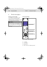
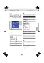
Page 6: ...and current are controlled in the servo amplifier Device description Fig 1 Front view section of LTU350 1 1 LC display 2 LED displays 3 Reset button 4 XDS1 interface for tightening spindle NOTE Further information on the equipment vari ants can be found in the operating instruc tions for the BT356 card rack or SB35x system box i XDS1 Reset 3 2 4 1 LTU350 book Page 20 Tuesday December 16 2008 12 24...

Page 7: ...ctual value Upper torque T Lower torque TI Relative torque upper T Relative torque lower TI Angle A Input IN Time t Yield point Yp Gradient G W OK 571 33 M 35 10 Table 2 Monitoring function Actual value Torque T Relative torque T Torque max value T Torque min value T Torque average value TA Torque range T Redundancy torque TR Tightening from above TCh Tightening from below TCl Angle A Total angle ...

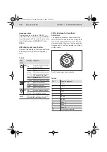
Page 8: ...ssion of interface signals is provided via this cable Fig 3 Socket view from front side Table 5 LED button Display Diagnosis BTB Off No power supply or LTU is in download mode Green Ready for operation Green flashing Not ready for operation but no system error emergency OFF has been triggered Red System error Orange VM supply module not ready TS Off Motor contactor open Green Ready for operation R...

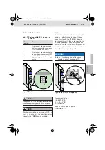
Page 9: ... Manufacturer Ferraz Shawmut Order No 6JX12 Table 7 Positions of the PIN plug in the LTU350 1 PIN plug in position Explanation 1 Operation of ErgoSpin as hand held nutrunner without emergency OFF condition on delivery 2 Operation of ErgoSpin as tighten ing spindle with emergency OFF via the VM350 supply module BS350 VM350 emergency OFF active NOTE The position of the PIN plug is verified with the ...

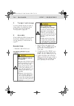
Page 10: ...t Make sure that the front panel is flush to the BT356 card rack or SB35x system box by tightening the knurled bolts CAUTION Risk of damage to persons and property Assembly of the LTU350 1 servo amplifier requires basic mechani cal and electrical knowledge yOnly qualified personnel see Personnel qualifications on page 18 are authorized to as semble the LTU350 1 servo amplifier yMeasures to prevent...

Page 11: ... 28 for the addresses of our foreign subsidiaries 10 Decommissioning For details on how to disassemble or replace the LTU350 1 servo amplifier please refer to chapter 11 Disassembly and replacement on page 26 CAUTION Risk of damage to persons and property Commissioning of the LTU350 1 servo amplifier requires basic me chanical and electrical knowl edge yOnly qualified personnel see Personnel quali...

Page 12: ...l 13 Extension and conversion Do not convert the LTU350 1 servo amplifier 14 Troubleshooting Malfunctions and information on errors are displayed on the display see section Display on page 21 by the LED on the front see section LED display and reset button on page 21 in the tightening system via the BS350 Should you be unable to remedy an occurring defect please contact one of the addresses found ...

Page 13: ...connected motor max 12 A 50 A Maximum line length to motor 100 m Interference suppression EN 55011 class A industrial area Interference immunity IEC 1000 4 part 2 to part 5 severity level 4 Permissible ambient temperature 0 to 55 C with fan Admissible relative humidity during operation 20 90 non condensing Admissible storage temperature 20 C to 70 C Admissible relative storage humidity 20 95 Prote...

Reviews: