background image

Instruction manual 

RE 92110-01-B/2022-03-22, EN

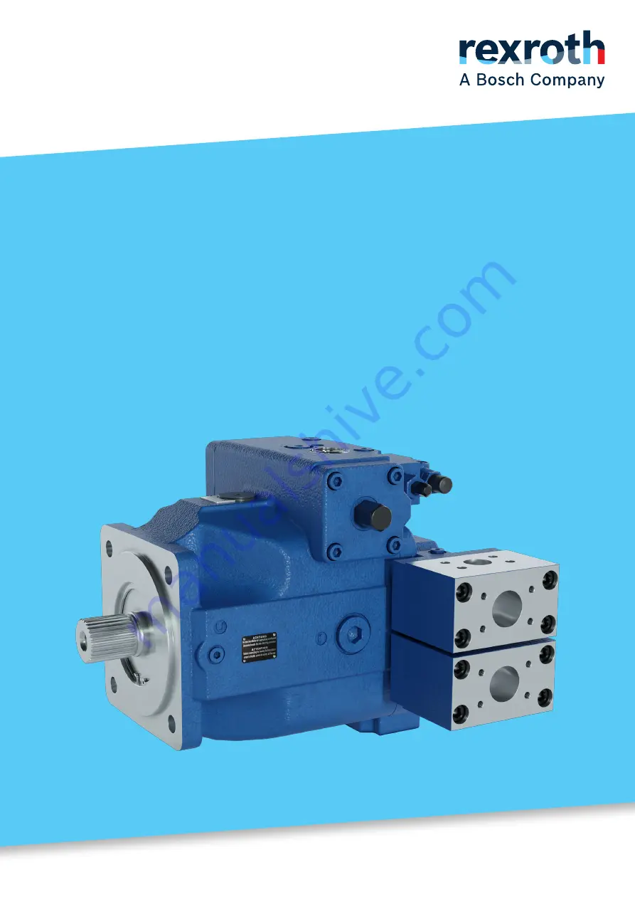
Axial piston 

variable pump

A4VSH series 1x and 30

Summary of Contents for rexroth A4VSH Series

Page 1: ...Instruction manual RE 92110 01 B 2022 03 22 EN Axial piston variable pump A4VSH series 1x and 30 ...

Page 2: ...ements concerning a certain condition or suitability for a certain application can be derived from our information The information given does not release the user from the obligation of own judgment and verification It must be remembered that our products are subject to a natural process of wear and aging The cover shows an example application The product delivered may differ from the image on the...

Page 3: ...l piston unit layout 20 5 2 2 Functional description 21 5 3 Product identification 22 6 Transport and storage 23 6 1 Transporting the axial piston unit 23 6 1 1 Transport by hand 23 6 1 2 Transport with lifting devices 24 6 2 Storing the axial piston unit 25 7 Assembly 27 7 1 Unpacking 27 7 2 Installation conditions 27 7 3 Installation position 29 7 3 1 Below reservoir installation standard 30 7 3...

Page 4: ... Maintenance and repair 50 10 1 Cleaning and care 50 10 2 Inspection 50 10 3 Maintenance 51 10 4 Repair 51 10 5 Spare parts 52 11 Removal and replacement 53 11 1 Required tools 53 11 2 Preparing for removal 53 11 3 Performing the removal 53 11 4 Preparing the components for storage or further use 53 12 Disposal 54 13 Extension and conversion 55 14 Troubleshooting 56 14 1 How to proceed for trouble...

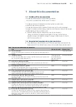
Page 5: ... request the installation drawing from your contact at Bosch Rexroth Installation drawing Axial piston variable pump A4VSH Contains the permissible technical data ports main dimensions and circuit diagrams of standard versions 92110 Data sheet Control devices DR DP FR and DFR Describes the control devices pressure control pressure control for parallel operation flow controller and pressure flow co...

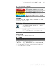
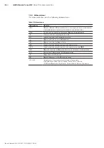
Page 6: ...reservation 90312 Data sheet 1 3 Representation of information Uniform safety instructions symbols terms and abbreviations are used throughout this documentation to ensure safe and proper use of the product For clarification they are explained in the sections below 1 3 1 Safety instructions This documentation contains safety instructions in chapter 2 6 Product specific safety instructions on page ...

Page 7: ...symbols indicate notices that are not safety relevant but increase understanding of the documentation Table 3 Meaning of symbols Symbol Meaning If this information is disregarded the product cannot be used and or operated to its full extent Single independent action 1 2 3 Numbered instruction The numbers indicate that the actions must be completed in order 1 3 3 Designations This documentation use...

Page 8: ...ng on one side EO Hydraulic control with proportional valve HD Hydraulic control pressure dependent HM Hydraulic control volume related HS5 Digital electro hydraulic control with control valve HS5E Digital electro hydraulic control with control valve and OBE DIN Deutsches Institut für Normung German Institute for Standardization ISO International Organization for Standardization JIS Japan Industri...

Page 9: ... hydrostatic drives in semi closed circuit Observe the technical data the application and operating conditions and the performance limits as specified in the data sheet 92110 and in the order confirmation Information about approved hydraulic fluids can be found in data sheet 92110 The axial piston unit is only intended for commercial use and not for private use Intended use includes having fully r...

Page 10: ...riate safety measures Skilled personnel must follow the rules relevant to their field and have the necessary hydraulic expert knowledge Hydraulic expert knowledge includes Being able to read and fully understand hydraulic circuit diagrams In particular fully understanding the relationships with regard to safety devices Knowledge regarding the function and interaction of hydraulic components Bosch ...

Page 11: ...g the axial piston unit with a bare shaft end Check whether or not your machine requires additional safety measures for your application If necessary make sure these are appropriately implemented Depending on the type of control used electromagnetic effects can be produced when using solenoids Applying a direct voltage signal DC to solenoids does not create electromagnetic interference EMI nor is ...

Page 12: ...e g crushing or fracture or damage to the product Make sure that the load bearing capacity of the lifting device is sufficient to safely bear the weight of the axial piston unit Never step or grip under suspended loads Ensure a stable transport position Use your personal protective equipment e g safety goggles safety gloves suitable working clothes safety shoes Use suitable lifting devices for tra...

Page 13: ... a cloth Hydraulic fluid will explode when making contact with water Explosion and fire hazard Do not bring hot hydraulic fluids in contact with water Electrical voltage Danger to life or risk of injury due to electric shock or property damage Always disconnect the voltage supply to the relevant machine system part before installing the product and or connecting or disconnecting the connector Prot...

Page 14: ...piston unit Risk of getting burnt Allow the axial piston unit to cool down sufficiently before touching it Wear heat resistant protective clothing e g gloves Improper cable and line routing Risk of stumbling and property damage Improper routing of cables and lines can cause a risk of stumbling as well as damage to equipment and components e g due to lines and connectors being torn off Always lay c...

Page 15: ...ns A4VSH series 1x and 30 15 64 2 7 Personal protective equipment Personal protective equipment is the responsibility of the user of the axial piston unit Observe the safety regulations in your country All pieces of personal protective equipment must be intact ...

Page 16: ...make sure that the rotary group has sufficient lubrication When commissioning a machine system make sure that the housing area and the working lines of the axial piston unit are filled with hydraulic fluid and remain filled during operation Avoid air inclusions in the forward drive shaft bearing especially with the axial piston unit installed with the drive shaft upward Check the hydraulic fluid l...

Page 17: ... Before commissioning ensure that all hydraulic connections are tight and that all seals and plugs of the plug in connection are correctly installed and undamaged to prevent fluids and foreign particles from entering the product Filter the hydraulic fluid when filling the system with a suitable filter system to minimize the solid particle contamination and water in the hydraulic system and to achi...

Page 18: ...on and contamination of ground water Always place a drip tray under the axial piston unit when filling and draining hydraulic fluid Use a suitable binding agent to collect any leaked hydraulic fluid Observe the parameters in the safety data sheet for the hydraulic fluid and the specifications provided by the machine system manufacturer Danger from hot components Nearby products can be damaged Comp...

Page 19: ...30 19 64 4 Scope of delivery 1 1 1 2 3 2 1 Fig 1 Axial piston unit Included in the scope of delivery Axial piston unit as per order confirmation The following parts come assembled on the unit Protective covers 1 Protective plug threaded plugs 2 Protective cover for through drive 3 ...

Page 20: ...ly by controlling the swashplate cradle 11 For axial piston units with swashplate design the pistons 9 are arranged axially relative to the drive shaft In the semi closed circuit the hydraulic fluid flows from the hydraulic pump to the consumer then directly back to the hydraulic pump There is then a high pressure side 5 and a low pressure side 6 which can change according to loading Missing hydra...

Page 21: ... of the cylinder chamber and into the hydraulic system by the pistons At the same time hydraulic fluid flows into the growing piston chamber on the low pressure side 6 In a semi closed circuit this is supported by the return flow and boost pressure or the anti cavitation valves The swivel angle of the cradle 11 is infinitely variable Controlling the swashplate swivel angle changes the piston strok...

Page 22: ...45678 xxxxxxxxxxxx MNR FD A4VSH125DR 30R VPB02N00 03W21 1 5 2 3 4 9 10 11 12 6 7 8 13 14 Fig 3 Name plate A4VSH 1 Trademark 2 Manufacturing date 3 Internal plant designation 4 Direction of rotation viewed on drive shaft here clockwise 5 Bar code 6 Power setting 7 Rotational speed 8 Flow setting 9 Pressure controller setting 10 Maximum displacement 11 Serial number 12 Material number of the axial p...

Page 23: ...tion drawing request if necessary Height mm Depth mm Weight may vary by equipment 6 1 1 Transport by hand Up to a specific maximum weight axial piston units can be transported by hand for a short distance Observe the national regulations in your country To prevent health damage we recommend renouncing any transport by hand CAUTION Risk of injury due to heavy loads Health hazard from carrying axial...

Page 24: ...ye bolt can bear the total weight of the axial piston unit plus 20 You can lift the axial piston unit as shown in Fig 4 with the eye bolt screwed into the drive shaft Fig 4 Mounting the eye bolt WARNING Danger due to suspended loads During transport with lifting strap the axial piston unit can topple out of the lifting strap and cause injury Use the widest possible lifting strap Make sure that the...

Page 25: ...perature 60 C Keep out of direct sunlight Do not stack axial piston units and store them in a shock proof manner Do not store the axial piston unit on the drive shaft or assembled parts e g sensors or valves For further storage conditions see Table 7 Check the axial piston unit monthly to ensure professional storage The axial piston units come in corrosion protection packaging corrosion protection...

Page 26: ...instructions only refer to axial piston units operated with mineral oil based hydraulic fluid Other hydraulic fluids require other specific preservation measures In such a case consult your local contact person you can find their contact information at https addresses boschrexroth com Bosch Rexroth recommends the following procedure 1 Clean the axial piston unit see chapter 10 1 Cleaning and care ...

Page 27: ... and completeness see chapter 4 Scope of delivery on page 19 Dispose of the packaging in accordance with the regulations in your country 7 2 Installation conditions The installation position and location of the axial piston unit essentially determine how it is installed and commissioned such as when filling and air bleeding the axial piston unit Fasten the axial piston unit so that the expected fo...

Page 28: ...ssible suction pressure of the boost pump used The different data sheets for the attachment pumps are listed in data sheet 92110 0 2 0 8 abs 1 2 3 0 0 1 2 1 2 1 SB SA U K B A Fig 6 Suction pressure 1 Absolute pressure gauge 2 Standard pressure gauge relative The suction conditions improve with below and inside reservoir installation Make sure that the working environment at the installation site i...

Page 29: ...filling and air bleeding easier With the installation position drive shaft upward a bearing flushing is needed to lubricate the front bearing and the shaft seal at port U installation position 6 8 and 14 Notes regarding series 30 When using external bearing flushing the throttle screw in port U must be turned in to the end stop To achieve an optimum control function the stroking chambers must be b...

Page 30: ... K2 3 U SB SA U K B A F Fig 7 Below reservoir installation A4VSH with installation position 1 6 K2 K3 Drain port T R L Filling air bleeding F Filling air bleeding U Bearing flushing SA Anti cavitation valve port SB Anti cavitation valve port ht min Minimum required immersion depth 200 mm hmin Minimum required distance to reservoir bottom 100 mm SB Baffle baffle plate Table 8 Below reservoir instal...

Page 31: ...uid level is equal to or below the upper edge of the pump see chapter 7 3 3 Above reservoir installation on page 32 Axial piston units with electric components e g electric controls sensors must not be installed in a reservoir below the fluid level Exceptions are control HS5M and EO2M The proportional valve can be positioned separately in the system and piped up via the designated ports X1 and X2 ...

Page 32: ... up Bearing flushing at port U required see data sheet 92110 T U T U 7 3 3 Above reservoir installation Above reservoir installation means that the axial piston unit is installed above the minimum fluid level of the reservoir Above reservoir installation is only possible at size 40 to 125 and should be avoided at size 250 Ensure that the axial piston pump with above reservoir installation has a mi...

Page 33: ...d immersion depth 200 mm hmin Minimum required distance to reservoir bottom 100 mm hES min Minimum height required to prevent axial piston unit from draining 25 mm SB Baffle baffle plate Table 10 Above reservoir installation Installation position Air bleed Filling 9 drive shaft horizontal R L F R L F 10 drive shaft horizontal T F T F 11 drive shaft horizontal K2 F K2 F 12 drive shaft horizontal K3...

Page 34: ... the direction of rotation of the axial piston unit as viewed on the drive shaft see chapter 5 3 Product identification on page 22 For information on the direction of rotation of the drive motor please refer to the drive motor manufacturer s instruction manual 7 4 2 Dimensions For standard versions the data sheet 92110 contains all required installation dimensions as well as the position and dimen...

Page 35: ...f the axial piston unit With a coupling On a gearbox On a cardan shaft 7 4 4 Installation with a coupling The following describes how to install the axial piston unit with a coupling NOTICE Danger from improper handling Product can be damaged Do not install the coupling hub on the drive shaft of the axial piston unit by striking it 1 Install the specified coupling half on the drive shaft of the ax...

Page 36: ...on with cardan shaft Bring the axial piston unit to the installation position and fasten it Details of the required tools and tightening torque for the mounting bolts can be obtained from the machine system manufacturer NOTICE Damage to the axial piston unit and leaks at the shaft seal due to incorrectly installed cardan shaft Improperly installed cardan shafts generate unbalances This results in ...

Page 37: ...nd 30 on page 40 Failure to do so could lead to malfunctions or damage If a port is not being used plug it with a threaded plug since the protective plugs are not pressure resistant Adjusting the setting screws will render the warranty void If you need to change the settings please contact your local contact person you can find their contact information at https addresses boschrexroth com 3 For ve...

Page 38: ...issible pressures of the respective ports see Table 11 Ports A4VSH series 1x and 30 on page 40 The machine system manufacturer is required to ensure that the connecting elements and lines correspond to the specified application conditions pressure flow hydraulic fluid temperature with the necessary safety factors Connect only hydraulic lines that are match the axial piston unit port pressure level...

Page 39: ...can imperial and the Japanese measuring system JIS Japan Industrial Standard Various kinds of seals are also used The system of units the kind of seal and the size of female thread and stud ends e g threaded plug must all match There is a risk of confusion due to the limited ways of visually telling them apart WARNING Leaky and bursting stud ends For fittings if a stud end that does not match the ...

Page 40: ...nd 30 Ports1 pmax bar 2 State3 A B Working port high pressure series 400 O SA SB Anti cavitation valve port A B 16 O MB Measuring port working pressure B 400 X MA Measuring port suction pressure A 400 X K2 K3 Flushing port 4 X4 T Drain port 4 X4 R L Drain port 4 O4 U Flushing port 4 X4 X Pilot pressure 350 O M M1 M2 Control pressure measuring 350 X P Control pressure 350 O RKV Control fluid return...

Page 41: ... fittings used Female threads in the axial piston unit The max permissible tightening torques MG max are the maximum values for the female threads and should not be exceeded For values see Table 12 Threaded plugs For the metallic threaded plugs supplied with the axial piston unit the required tightening torques of threaded plugs MV apply For values see Table 12 Mounting bolts For mounting bolts wi...

Page 42: ...0 Nm 135 Nm1 12 mm M33 2 540 Nm 225 Nm1 17 mm M42 2 720 Nm 360 Nm1 22 mm M48 2 900 Nm 400 Nm1 24 mm ISO 11926 5 16 24 UNF 2B 10 Nm 7 Nm 1 8 in 3 8 24 UNF 2B 20 Nm 10 Nm 5 32 in 7 16 20 UNF 2B 40 Nm 18 Nm 3 16 in 9 16 18 UNF 2B 80 Nm 35 Nm 1 4 in 3 4 16 UNF 2B 160 Nm 70 Nm 5 16 in 7 8 14 UNF 2B 240 Nm 110 Nm 3 8 in 1 1 16 12 UN 2B 360 Nm 170 Nm 9 16 in 1 5 16 12 UN 2B 540 Nm 270 Nm 5 8 in 1 5 8 12 ...

Page 43: ...very combination of connecting pieces couplings or connecting points with hoses or pipes to ensure they are in safe working condition For relationship between direction of rotation and flow direction see data sheet 92110 7 4 9 Electrically connecting the axial piston unit NOTICE Short circuit due to penetrating hydraulic fluid Fluid can penetrate the product and cause a short circuit Do not instal...

Page 44: ...his proceed as follows 1 Loosen the mounting nut 1 of the solenoid To do this turn the mounting nut 1 one turn counterclockwise 2 Turn the solenoid body 2 to the desired position 3 Re tighten the mounting nut Tightening torque of the mounting nut 5 1 Nm width across flats SW26 12kt DIN 3124 On axial piston units with a Hirschmann connector according to DIN EN 175 301 803 A ISO 4400 the following t...

Page 45: ...ed in chapter 2 Safety instructions on page 9 Connect the pressure gauge for the boost pressure working pressure case pressure and suction pressure to the specified measuring points on the axial piston unit or in the hydraulic system to check the technical data during initial operation During commissioning monitor the temperature of the hydraulic fluid in the reservoir to ensure that it lies withi...

Page 46: ...ficient for the requirements of our components Use a suitable filter system to filter hydraulic fluids during filling to minimize solid particle contamination and water in the hydraulic system 2 Fill and air bleed the axial piston unit via the appropriate ports see chapter 7 3 Installation position on page 29 Also fill the hydraulic lines of the system NOTICE Risk of property damage due to inadequ...

Page 47: ...nd can withstand the max pressure 5 Check the suction pressure at port SA and SB of the axial piston pump at nominal speed and max swivel angle Refer to data sheet 92110 for the permissible value 6 At maximum working pressure check the case pressure at port T K2 K3 or R L Refer to data sheet 92110 for the permissible value 8 1 3 Performing a functional test WARNING Improperly connected axial pisto...

Page 48: ...hours The mechanical hydraulic efficiency is also greater until the running in phase of about 10 operating hours is concluded To ensure that contamination in the hydraulic system does not damage the axial piston unit Bosch Rexroth recommends the following procedure after the running in phase After the running in phase have a hydraulic fluid sample analyzed for the required cleanliness level Change...

Page 49: ...s no settings or changes during operation For this reason this chapter of the manual does not contain any information on adjustment options Use the product only within the performance range specified in the technical data The machine system manufacturer is responsible for proper project planning of the hydraulic system and its control ...

Page 50: ...oisture can penetrate into the axial piston unit during cleaning Use only water and if necessary a mild cleaning agent to clean the axial piston unit Never use solvents or aggressive cleaning agents Remove major external contamination and keep clean sensitive and important components such as solenoids valves indicators and sensors 10 2 Inspection In order for the axial piston unit to be reliable a...

Page 51: ... every 2000 operating hours whichever occurs first or having it analyzed by the hydraulic fluid manufacturer or a laboratory to determine its suitability for further use The service life of the axial piston unit is limited to the service life of the bearings used if the permissible operating parameters are observed You can ask your local contact person about service life based on load cycle You ca...

Page 52: ...its are order specific When ordering spare parts specify the material and serial number of the axial piston unit as well as the material numbers of the spare parts Address all questions regarding spare parts to your proper Bosch Rexroth Service partner or the service department of the manufacturer s plant of the axial piston unit Details for the manufacturer s plant can be found on the name plate ...

Page 53: ... Performing the removal Proceed as follows to remove the axial piston unit 1 Make sure you have the appropriate tools and wear personal protective equipment 2 Allow the axial piston unit to cool down until it can be removed without danger 3 For below reservoir installation before removing the axial piston unit seal the connection to the reservoir and or drain the reservoir 4 Place a drip tray unde...

Page 54: ...etely drain the axial piston unit 2 Dispose of the axial piston unit and packaging material in accordance with the regulations in your country 3 Dispose of the hydraulic fluid in accordance with the regulations of your country Also observe the applicable safety data sheet for the hydraulic fluid 4 Disassemble the axial piston unit into its constituent parts for proper recycling 5 For example separ...

Page 55: ...e made using the product specific setting instructions The warranty from Bosch Rexroth only applies to the configuration as delivered Any modification extension or software customization voids the warranty Setting screws are protected against unauthorized adjustment by tamper proof caps Removal of the tamper proof caps will void the warranty If you need to change the settings please contact your l...

Page 56: ... your product functions in conjunction with the entire system Try to find out whether or not the product was working properly in conjunction with the entire system before the fault occurred Try to determine any changes to the entire system in which the product is installed Have there been any changes to the application conditions or operating range of the product Has maintenance work recently been...

Page 57: ...tion see chapter 7 4 1 Preparation on page 33 Improper mounting of the axial piston unit Check the mounting of the axial piston unit according to the specifications of the machine system manufacturer observe tightening torques Improper mounting of assembled parts hydraulic lines or improper installation of the coupling Fasten assembled parts according to the parameters provided by the coupling fit...

Page 58: ...on filter too small or blocked etc Machine system manufacturer Check the system e g optimize inlet conditions use suitable hydraulic fluid Fill the suction line with hydraulic fluid Remove foreign particles from the suction line Check the filter system and change the filter as necessary Hydraulic fluid not in optimal viscosity range Machine system manufacturer Check temperature range and use suita...

Page 59: ...ocked etc Machine system manufacturer Check the system e g optimize inlet conditions use suitable hydraulic fluid Fill the suction line with hydraulic fluid Remove foreign particles from the suction line Check the filter system and change the filter as necessary Hydraulic fluid not in optimal viscosity range Machine system manufacturer Check temperature range and use suitable hydraulic fluid Insuf...

Page 60: ...e pressure relief valves and pressure control valves in the axial piston unit boost pressure relief valve high pressure relief valve Air bleed the axial piston unit and hydraulic system Contact Bosch Rexroth Service Unstable control signal Contact machine system manufacturer or Bosch Rexroth Service Malfunction in the control devices or the controller Contact Bosch Rexroth Service Excessively high...

Page 61: ...echnical data A4VSH series 1x and 30 61 64 15 Technical data The data sheet can be found in the online product catalog at www boschrexroth com p A4VSH Order related technical data for your axial piston unit can be found in the order confirmation ...

Page 62: ...or plate 20 Drive shaft 20 E Eye bolt 24 F Filling 45 Flushing cycle 44 Functional description Control 21 Motor function 21 Functional test 47 I Identification 22 Inside reservoir installation 31 Inspection 50 Installation On gearbox 36 With cardan shaft 36 With coupling 35 Installation conditions 27 Installation position Above reservoir installation 32 Below reservoir installation 30 Inside reser...

Page 63: ...ning in phase 48 S Safety instructions 9 General 10 Product specific 12 Signal word 6 Scope of delivery 19 Solenoid position Changing 44 Spare parts 52 Storage 23 25 Storage time 25 Stroking piston 20 Suction side 20 Symbols 7 T Technical data 61 Tightening torques 41 Tools 53 Transport 23 By hand 23 with eye bolt 24 with lifting strap 24 Transporting 23 Transport protection 37 Troubleshooting 56 ...

Page 64: ...terwiesen 14 72160 Horb a N Germany Tel 49 0 7451 92 0 sales industry horb boschrexroth de www boschrexroth com Subject to change RE 92110 01 B 2022 03 22 Your local contact person can be found at https addresses boschrexroth com ...

Reviews: