


About this product 21/68
RE 92004-01-B/05.2017, A4VG Series 40,
Bosch Rexroth AG
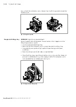
5.2.2 Functional description
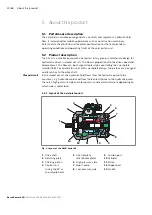
Torque and rotational speed are applied to the drive shaft (
1
) by a drive motor. The
drive shaft is connected by splines to the cylinder (
10
) to set this in motion. With
every revolution, the pistons (
11
) execute a stroke in the cylinder bores, the size of
which depends on the pitch of the cradle (
13
). The slipper pads (
12
) are held on
with the pistons and guided along the glide surface of the cradle by the retaining
plate (
2
).
The pitch of the swashplate during a rotation causes each piston to move over the
bottom and top dead centers and back to its initial position.
Here, hydraulic fluid is fed in and drained out through the two control slots in the
control plate (
5
) according to the stroke displacement. On the high-pressure side
(
6
) the hydraulic fluid is pushed out of the cylinder chamber and into the hydraulic
system by the pistons. At the same time, hydraulic fluid flows into the growing piston
chamber on the low-pressure side (
8
). In a closed circuit, this is supported by the
return flow and boost pressure.
The working pressure is limited by the pressure cut-off.
The pressure cut-off corresponds to a pressure control which reduces the pump
capacity once the set specified pressure command value is reached so that the set
pressure is maintained but not exceeded.
The two high-pressure relief valves protect the hydrostatic transmission (pump and
motor) from overloading. They limit the maximum pressure in the respective high-
pressure line and serve simultaneously as boost valves. High-pressure relief valves
are not working valves and are only suitable for pressure peaks or high rates of
pressure change.
The boost pump (
7
) continuously supplies a sufficient volume of fluid (boost volume)
from a small reservoir to the low-pressure side of the closed circuit via a check valve
to replenish the internal leakage of the variable pump and consumer. The boost
pump is an internal gear pump which is driven directly via the drive shaft.
In order to replenish the internal leakage in the variable pump and consumers,
port
G
must be connected to an external source of boost pressure. The boost-
pressure relief valve is integrated.
The optional sequence valve interrupts the active control pressure. The springs in
the stroking chambers move the stroking piston (
3
) towards the central position
(neutral position). The reset function is influenced by the current working pressure
and the rotational speed.
Switching off the control pressure does not ensure that the pump goes to the central
position (neutral position).
▶
Use an appropriate emergency-off device to ensure that the drive can be brought
to a safe position at any time. The machine or system manufacturer is responsible
for the installation of a proper emergency-off device.
Pump function
Pressure cut-off
High-pressure limitation
Version with boost pump
Version without boost
pump (external boost
pressure supply)
Sequence valve
(optional)