background image


A range hood fitted above the top must be installed 
according to the installation instructions for the range 
hood. A minimum distance of 650 mm is required for a 
range hood and 750 mm for an exhaust fan.

Minimum thickness of benchtop is 30 mm. See Fig. 2.

Installation procedure:

Clearances

2

Installation of 
cooktop into the 
kitchen bench

30 mm
minimum

Any adjoining wall surface situated within 200mm from the 
edge of any hob burner must be  a  suitable  non-com-

If the base of the hotplate can be touched, a protecting
shield must be fitted.  This  shield  must  be  at  least 
10mm from the lowest part of the hotplate  and  must 

be capable of withstanding the appliance temperatures. 

bustible

 material for a height of 150mm for the entire

length of the hob. Any combustible construction above

the hotplate must be at least 650mm above the top of

the burner and no cons

 above the top of the  

 truction  shall   be   

within 4 50mm

.

burner

 A minimum depth of 50mm from the top of the 

worktop


surface must be provided for the a

ppliance.

1. For cutout dimensions and clearances refer


2.

a) If the clamps and the selfadhesive seal (lower edge 

of the hob) are already fitted (depending on the model),  

keeps the entire work surface watertight and prevents

spilage from leaking into cupboards underneath. Slightly

do not under any circumstance remove them. The seal

losen the retaining screws of the clamps positioned at

the bottom of the cooktop.


     b ) If the clamps and the selfadhesive seal have not

the gas burner covers from your cooking hob and turn it 

upside down. Now fit the selfadhesive seal supplied

with the appliance onto the lower edge of the hob. Take 

the clamps and screw them into the lower point designed

been fitted in the factory, remove the pan support and

for this purpose. See Fig. 3.

Side clearances: If the distance measured from the


periphery of the  nearest burner to any vertical surface


is less than 200 mm, the surface shall be protected in 

accordance with clauses 5.12.1.1 & 5.12.1.2 of AS 5601.

Fig.1

.

7

Summary of Contents for PHL206FAU

Page 1: ... Straße 34 81739 München Robert Bosch Hausgeräte GmbH Internet http www bosch hausgeraete de This cooktop is for use with Natural Gas and Universal LPG PHW206FAU PHL206FAU PPH626B90A PPQ726B90A Cod 9000005546 C ...

Page 2: ...ransportation All the material used for packing is considered essential for this purpose and is also completely recyclable You too can contribut towards protecting the environment by disposing of this material at your nearest recyclable refuse collection point Do not dispose of used cooking oil down the kitchen sink Oil may seriously damage the environment Dispose of it in a closed container at yo...

Page 3: ... Connection Electrical connection Gas connection To change injectors Minimum flame adjustment Injector size chart Operating instructions Burner ignition control Burner location User instructions Warnings concerning cooking Cleaning and maintenance Service Trouble shooting Wiring diagram 8 9 9 7 7 6 6 4 4 4 10 11 11 12 12 13 13 13 14 15 16 17 18 19 18 Conversion front Nat Gas to Universal LPG 3 ...

Page 4: ...ame is out does not mean parts cannot still be hot 3 This appliance shall not be used for space heating This instruction is based on safety considerations 4 Be sure to disconnect the electrical supply before disass embly of the appliance 5 Keep the appliance area clear and free from combustible materials gasoline and other flammable vapours and liquids 6 This appliance must be installed in a posit...

Page 5: ...d become detached call the Service Centre immediately for them to repair or repplace it 22 While using your gas should avoid draughts and spillages of cold liquids As these may cause the glass to break Note To avoid jeopardising the electrical safety of the appliance it is forbidden to use high pressure or steam jet cleaning SHOULD THE RELEVANT CONDITIONS NOT BE PROPERLY SATISFIED THE INSTALLER AN...

Page 6: ...plied for adhesion to accessed when the hotplate is installed label on the base of the hotplate cannot be 590 Universal LPG Universal LPG Natural gas Natural gas This installation must conform with the following Manufacturer s Installation instructions Local Gas Fitting Regulations Municipal Building Codes AGA Installation Code for Gas Burning Appliances S A A Wiring Code Local Electrical Regulati...

Page 7: ...ll be within 450mm burner A minimum depth of 50mm from the top of the worktop surface must be provided for the appliance 1 For cutout dimensions and clearances refer 2 a If the clamps and the selfadhesive seal lower edge of the hob are already fitted depending on the model keeps the entire work surface watertight and prevents spilage from leaking into cupboards underneath Slightly do not under any...

Page 8: ... should turn the clips and 4 tighten the screw as shown in Fig 4 that the hob is resting on its entire perimeter 3 Place the hotplate on top of the bench cut out and press down firmly on all edges at the same time to ensure 3 3 8 ...

Page 9: ...he L tube from its factory set position If for some reason the L tube should be twisted it is necessary to make sure that this area is properly sealed Make sure that all connections performed are free of leakage The manufacture does not accept any liability for leakage on connections performed by the installer or if the L tube is moved Natural gas connection Pressure test point R 1 2 Pressure test...

Page 10: ...g or permanent deformation and should be able to be inspected along its entire length with the cooktop in the installed position Unions compatible with the hose fittings must be used and all connections tested for gas leaks The supply connection point shall be accessible with the appliance installed Before Leaving Check all connections for gas leaks with soap ensure correct operation of gas valves...

Page 11: ...85 0 97 0 93 To change injectors All work involved in installation setting and adaptation to a different gas type must be carried out by authorised personnel from our Service Centre and must comply with current regulations and the conditions laid down by the local gas company Request change over injectors from our customer service deparment refer injector chart below for sizes Coverting the cookto...

Page 12: ...mum flame position and back a few times screw must be fully tightened down clockwise 6 valve shaft in the event of damage change the entire valve 9 10 1 Turn the control knob to minimum 2 Remove the control knob from the valve spindle 3 4 The adjustment screw is positioned at the rear lower Minimum flame adjustment efit the control knob Never dismount the R Apply pressure with the tip of the screw...

Page 13: ...onds for any unburnt gas to disperse before repeating the ignition procedure described above To turn off the gas supply to a burner turn the control burner Low flame graphic lowest output Burner Position Graphic knob clockwise to the OFF position Refer Fig 12 12 If ignition fails depress knob and try again If flame is Turn anti clockwise to set the flame to the desired not established in 15 second...

Page 14: ...ooktop leads to the production of heat and moisture in the kitchen For this reason make sure that the room is properly ventilated Keep natural ventilation mechanical ventilation device e g a range hood or overhead exhaust fan An orangy flame is normal and simply indicates the presence of salt in the atmosphere from cooking If the flame has yellow patches this is Boiling burners hood or not a fault...

Page 15: ...ishes Large Steaks omelettes Rice white Steaming burner frying sauce and and ragout vegetables Medium Steaming potatoes Reheating keeping burner fresh vegetables things hot and making stews and pasta tasty casseroles Small Melting and slow caramels cooking butter chocolate vegetables and jelly fruits and Casseroles rice frozen products burner pudding and Defrosting ...

Page 16: ...ff centre They Do not use wide based re ceptacles on the burners nearest to the controls When centred on the bur ner they could touch the controls or raise the tempe rature in the area This may Do not use receptacles with uneven bases They leng then cooking times and in Do not place receptacles on burners off centre They Do not use wide based re ceptacles on the burners nearest to the controls Whe...

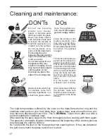
Page 17: ...Do not use knives scra pers or similar implements metal surrounds Do not slide recipients over Grains of sand which may for example come from cleaning vegetables can scratch the glass surface Cleaning and maintenance The high temperatures suffered by the cover on the triple flame burner ring and the stainless steel parts on your hob plate rings grease trays area around burners etc may become disco...

Page 18: ...ed properly Clean the gas ports on the If the gas flow does not seem normal or there is no gas flow The isolation valve is closed If the gas is supplied from a gas bottle it may be empty Open the isolation valve Replace the gas bottle with If the kitchen smells of gas One of the valves has been left open Check to see if a valve has Check that the coupling on the gas bottle is in order What s wrong...

Page 19: ... 0 85 HGC MJ Electrical compliance AGA approval number Preinstalled NG In compliance with AS 3100 Robert Bosch Hausgeräte GmbH CIF A 28 893550 Gas type Test point pressure kPa NG LP 1 0 2 75 Injectors sizes mm LHF LHR RHF RHR 1 65 0 93 1 18 0 67 0 90 0 50 1 60 0 85 HGC MJ Electrical compliance AGA approval number Preinstalled NG In compliance with AS 3100 E Nr Made in Spain 6962 Made in Spain 6962...

Reviews: