background image

6

This installation must conform with the following:

Manufacturer’s Installation instructions

Local Gas Fitting Regulations

Municipal Building Codes,

AGA Installation  Code for Gas Burning Appli-

ances. (AS 5601AG 601)

S.A.A. Wiring Code

Local Electrical Regulations

Any other statutory regulations

These built-in hobs are intended to be inserted in a

benchtop cutout.
Only an authorised person should connect the appli-

ance.
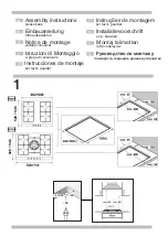
Installation dimensions are shown in Fig.1

Before connecting the unit, check whether the local

connection conditions (type of gas) are compatible

with the unit’s settings. Observe any special condi-

tions imposed by local suppliers (utilities). The specifi-

cations of this cooktop are stated on the data label

located on the bottom of the cooktop base.

Installation

1

11

Depress control knob and turn anti-clockwise to ‘High

flame’ position. Hold the knob down for a few sec-

onds until the flame ignites. Keep control knob de-

pressed for a few seconds to activate the flame failure

device. If ignition fails, depress knob again and wait

for ignition. Turn anti-clockwise to set the flame to the

desired intensity.
All burners are fitted with a flame failure device which

shuts off the gas supply if the flame extinguishes for

any reason. To re-ignite, wait 30 seconds for any

unburnt gas to disperse before repeating the ignition

procedure described above.
To turn off the gas supply to a burner turn the control

knob clockwise to the ‘OFF’ position. (Refer Fig. 14)

The control knob is used to adjust the flame of the gas

burner.
‘Low flame’ graphic =  lowest output
‘High flame’ graphic = highest output

Operating instructions

1. Small burner
2. Medium burner
3. Wok burner

4. Large burner
5. Medium burner
6. Control knobs

Burner ignition &

control

Preparing to install

Burner locations

13

14

Summary of Contents for PCL 785 FAU

Page 1: ...ATION INSTRUCTIONS MAINTENANCE INSTRUCTIONS This cooktop is for use with Natural and Propane gases Leave these instructions with the owner MAKERS WARRANTY BOSCH Booklet designed and produced by DESIGN MAXIM 03 0853 7491 BOSCH Part No W1531 Version Bosch A ...

Page 2: ...lbourne 1300 30 70 37 head office Sales Customer and Technical Service New Zealand 0800 4BOSCH 0800 426 724 Sales and Customer Service Robert Bosch Australia Pty Ltd Incorporated in Victoria ABN 48 004 315 628 Victoria Cnr Centre McNaughton Roads Clayton 3168 Phone 03 9541 5555 Fax 03 9541 5595 New Zealand 14 16 Constellation Drive Mairangi Bay Auckland 1310 Phone 09 478 6158 Fax 09 478 2914 Servi...

Page 3: ...d replace if faulty The automatic circuit Check to see if the circuit breaker or mains breaker or a differential has differential has been been triggered in the mains triggered supply box If the electronic ignition There may be food or The gap between the spark system does not work cleaning product plug and the burner needs to particles between the be cleaned carefullly spark plugs and the burners...

Page 4: ...ation air 7 Cabinets installed above the gas cooktop must have a minimum clearance of 650 mm 24 8 The gas pressure regulator supplied with the ap pliance must be installed in line with the gas pipe N G only 13 Do s Once the appliance is cold clean it with a sponge and soapy water Remove any spills immediately This will avoid unnecessary effort later Allow burners and trivets to cool down before cl...

Page 5: ... properly ventilated Keep natural ven tilation openings such as windows open or provide a mechanical ventilation device e g a range hood or overhead exhaust fan For safety and economic gas usage you should al ways use the correct pan on the correct burner Flames should not protrude beyond the base of the pan You will save energy time and money by always placing the correct pan size on the correct ...

Page 6: ...ss control knob and turn anti clockwise to High flame position Hold the knob down for a few sec onds until the flame ignites Keep control knob de pressed for a few seconds to activate the flame failure device If ignition fails depress knob again and wait for ignition Turn anti clockwise to set the flame to the desired intensity All burners are fitted with a flame failure device which shuts off the...

Page 7: ...ave a space at least 100mm between any drawer partition or oven that is installed underneath the cooktop Minimum thickness of benchtop is 15mm See Fig 2 Installation procedure 1 For cutout dimensions and clearances refer Fig 1 2 The hotplate is factory fitted with sealing tape around the lower edge of the hob and two pres sure clamps either side The seal keeps the entire work surface watertight an...

Page 8: ...and Fig 5 Direction of gas flow is indicated on the rear of the regulator For position of the inlet connection refer Fig 1 Natural gas connection Propane gas connection Connection Installation continued 9 It should be expressly noted that we cannot accept any liability for direct or indirect damage caused by wrong connection or improper installation When being repaired the appliance must always be...

Reviews: