background image

English 2                                                                                                                                                     9001079091 RevA

9

IMPORTANT SAFETY INSTRUCTIONS

READ AND SAVE THESE INSTRUCTIONS

INSTALLER:

 LEAVE THESE INSTRUCTIONS WITH THE 

APPLIANCE AFTER INSTALLATION IS COMPLETE.

IMPORTANT:

 SAVE FOR THE LOCAL INSPECTOR'S 

USE.

OWNER:

 PLEASE RETAIN THESE INSTRUCTIONS FOR 

FUTURE REFERENCE.

Important Safety Instructions

WARNING: 

Do not repair or replace any part of the appliance unless 
specifically recommended in the manuals. Improper 
installation, service or maintenance can cause injury or 
property damage. Refer to this manual for guidance. All 
other servicing should be done by a qualified technician. 

Gas Appliance Safety

Install a gas shutoff valve near the appliance. It must 
be easily accessible in an emergency.

Leak testing must be conducted by the installer 
according to the instructions in this manual.

The appliance and its individual shutoff valve must be 
disconnected from the gas supply piping system during 
any pressure testing at pressures in excess of ½ psi 
(3.5 kPa).

The appliance must be isolated from the gas supply 
piping system by closing its individual manual shutoff 
valve during any pressure testing of the gas supply 
piping system at test pressures equal to or less than ½ 
psi (3.5 kPa)

The minimum supply pressure must be 1" water 
column above the manifold pressure printed on the 
data plate. 

The maximum supply pressure must not exceed 14.0 
inches water column (34.9Millibars).

For Massachusetts installations: 

Installation must be performed by a qualified or 
licensed contractor, plumber or gas fitter qualified 
or licensed by the state, province or region where 
this appliance is being installed.

Shut-off valve must be a "T" handle gas cock.

Flexible gas connector must be new and not longer 
than 36 inches.

Installer - show the owner where the gas shut-off valve 
is located.

Propane Gas Installation

The propane gas tank must be equipped with its own 
high pressure regulator. In addition, the regulator 
supplied with this unit must also be used. 

The appliance is shipped from the factory for use with 
natural gas. It must be converted for use with propane. 
A qualified technician or installer must do the 
conversion.

Equipment and Usage Safety Requirements

The cooktop must be used in conjunction with a 
suitable ventilation system.

Remove all tape and packaging before using the 
appliance. Destroy the packaging after unpacking the 
appliance. Never allow children to play with packaging 
material. 

Never modify or alter the construction of the appliance. 
For example, do not remove panels, wire covers or 
screws.

To eliminate the risk of burns or fire by reaching over 
heated surface units, cabinet storage space located 
above the surface units should be avoided. If cabinet 
storage is to be provided, the risk can be reduced by 
installing a hood that projects horizontally a minimum of 
5 inches beyond the bottom of the cabinet.

Verify that cabinets above the cooktop are a maximum 
of 13" (330 mm) deep.

Appliance Handling Safety

Unit is heavy and requires at least two people or proper 
equipment to move. 

Hidden surfaces may have sharp edges. Use caution 
when reaching behind or under appliance.

Safety Codes and Standards

This appliance complies with one or more of the 
following Standards:

ANSI Z21.1, Household Cooking Gas 
Appliances

It is the responsibility of the owner and the installer to 
determine if additional requirements and/or standards 
apply to specific installations.

Installation must conform with local codes or, in the 
absence of local codes, with the National Fuel Gas 
Code, ANSI Z223.1/NFPA 54.

The appliance must be electrically grounded in 
accordance with local codes or, in the absence of local 
codes, with the National Electrical Code ANSI/ NFPA 
70, latest edition. In Canada, installation must be in 

Summary of Contents for NGM5055UC

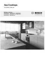
Page 1: ...Installation Manual Gas Cooktops NGM Gas Cooktops NGM5055UC NGMP055UC NGM5655UC NGM8055UC NGM8065UC NGM8655UC NGM8665UC NGMP655UC ...

Page 2: ......

Page 3: ...luded 4 General Information 4 Overall Dimensions 4 Preparation 4 Electrical Requirements 4 Gas Requirements 4 Cabinet Requirements 4 Countertop Requirements 5 Island Installation 5 Mounting Requirements 5 Ventilation Recommendations 5 Installation Procedure 6 Prepare the Countertop 6 Seal the Cooktop with Foam Tape 6 Install the Cooktop 6 Connect Gas Supply 7 Connect Electrical Supply 7 Burner Cap...

Page 4: ......

Page 5: ...r flammable vapors and liquids in the vicinity of this or other appliances WHAT TO DO IF YOU SMELL GAS Do not try to light any appliance Do not touch any electrical switch Do not use any phone in your building Immediately call your gas supplier from a neighbor s phone Follow the gas supplier s instructions If you cannot reach your gas supplier call the fire department Installation must be performe...

Page 6: ...as shut off valve is located Propane Gas Installation The propane gas tank must be equipped with its own high pressure regulator In addition the regulator supplied with this unit must also be used The appliance is shipped from the factory for use with natural gas It must be converted for use with propane A qualified technician or installer must do the conversion Equipment and Usage Safety Requirem...

Page 7: ...trical Code It is required that the cooktop be installed on a grounded non GFCI branch circuit Installer show the owner the location of the circuit breaker or fuse Mark it for easy reference Important Save these instructions for the local electrical inspector s use Before installing turn power OFF at the service panel Lock service panel to prevent power from being turned ON accidentally Be sure yo...

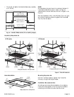
Page 8: ... its own high pressure regulator in addition to the pressure regulator supplied with this unit The cooktop is shipped from the factory for use with natural gas For use with LP conversion a qualified technician or installer must do the conversion Cabinet Requirements Dimension requirements in Figures 1 and 2 are for combustible surfaces When the surface is protected by a material listed by UL as a ...

Page 9: ...l the Cooktop on page 6 for further details Ventilation Recommendations We strongly recommend the installation of a ventilation hood above this appliance The hood must be installed according to instructions furnished with the hood Figure 1 Installed Dimensions from cooktop edges Depth from Back Wall Cabinet 13 33cm max Hood Depth 24 61cm max Centered Over Cooktop Rear Wall 2 5cm Right Side 12 33cm...

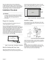
Page 10: ...eter of the cutout as shown by the dotted line in Figure 4 Counter Cutout Foam Tape Placement Leave 1 4 6 35mm gap between the foam tape and the edge of the cutout Install the Cooktop Insert cooktop into the cutout Attach clamps of the hold down brackets packaged with the cooktop Use the washer and screws provided Adjust hold down brackets to desired position and tighten screws to cooktop Insert a...

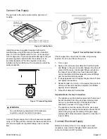
Page 11: ...s appearing around fittings and connections indicate a leak 3 If a leak appears turn off supply line gas shut off valve and tighten connections 4 Retest for leaks by turning on the supply line gas shut off valve When leak check is complete no bubbles appear test is complete 5 Wipe off all detection fluid residue Important Notes for Gas Connection The appliance and its individual gas shutoff valve ...

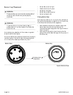
Page 12: ...he cap that corresponds to a letter A D or F cast in the burner base that is attached to the appliance After electrical connection is complete place each burner cap on its correct burner base per its corresponding letter designation See figure Burners Caps on page 8 Place burner cap gently on top of base so that the prongs of the burner base fit snugly into the groove of the burner cap 9 WARNING T...

Page 13: ...ide to check if it is properly placed If properly placed the cap will click from side to side as the prongs hit the groove ridge Install Burner Grates Properly position and install each burner grate as shown in the following illustrations The center grate will seat with rubber feet fitting to indentations in the cooktop surface Check to be sure the feet match the indentations Figure 10 Burner Cap ...

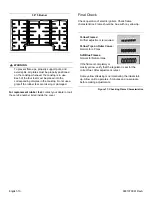
Page 14: ... in use Each of the four feet must be placed into the corresponding dimples in the cooktop Do not use a grate if the rubber feet are missing or damaged 36 5 Burner Figure 11 Checking Flame Characteristics Yellow Flames Further adjustment is required Yellow Tips on Outer Cones Normal for LP Gas Soft Blue Flames Normal for Natural Gas If the flame is completely or mostly yellow verify that the regul...

Page 15: ...er to the Statement of Limited Warranty in the Use and Care Manual See Use and Care Manual for troubleshooting information Product Data Plate The data plate shows the model and FD product s unique identifier for customer service number of your cooktop It is located on the underside of the cooktop Keep your invoice or escrow papers for warranty validation if service is needed Figure 12 Data Plate L...

Page 16: ...English 12 9001079091 RevA ...

Page 17: ... 1 Installation 4 Avant de commencer 4 Outils et pièces nécessaires 4 Pièces comprises 4 Informations générales 4 Préparation 4 Procédure d installation 6 Préparation du plan de travail 6 Scellement de la table de cuisson avec du ruban en mousse 6 Installation de la table de cuisson 6 Raccordement de l alimentation de gaz 7 Raccordement de l alimentation électrique 7 Mise en place des capuchons de...

Page 18: ......

Page 19: ...HU GH PDWLqUHV FRPEXVWLEOHV G HVVHQFH RX G DXWUHV YDSHXUV HW OLTXLGHV LQIODPPDEOHV j SUR LPLWp GH FHW DSSDUHLO RX GH WRXW DXWUH DSSDUHLO pOHFWURPpQDJHU 1H WHQWH G DOOXPHU DXFXQ DSSDUHLO 1H WRXFKH DXFXQ LQWHUUXSWHXU pOHFWULTXH 1 XWLOLVH DXFXQ WqOqSKRQH GDQV OH ORFDO SSHOH LPPpGLDWHPHQW OH IRXUQLVVHXU GH JD j SDUWLU GX WpOpSKRQH G XQ YRLVLQ 6XLYH OHV LQVWUXFWLRQV GX IRXUQLVVHXU GH JD 6L YRXV QH SDUY...

Page 20: ... doit être pourvu d une poi gnée en forme de T Le connecteur de gaz flexible doit être neuf et sa longueur ne doit pas dépasser 36 po 914 mm Installateur indiquez au propriétaire où se trouve le robinet d arrêt de gaz Installation du gaz propane Le réservoir de gaz propane doit être doté d un régulateur haute pression dédié En outre le régulateur fourni avec cet appareil doit être également utilis...

Page 21: ...llé conformément au Code national de l électricité National Electric Code ou au Code canadien de l électricité Canadian Electric Code Il est impératif que la table de cuisson soit installée sur un circuit de dérivation mis à la terre sans disjoncteur de fuite de terre Installateur indiquer au propriétaire l emplacement du disjoncteur ou du fusible Identifier sa position pour pouvoir le retrouver f...

Page 22: ... cet appareil La table de cuisson est réglée à sa sortie de l usine pour fonctionner au gaz naturel Pour une utilisation avec le kit de conversion au GPL cette conversion doit être effectuée par un technicien ou installateur qualifié Exigences concernant les armoires Les exigences en matière de dimensions décrites aux figures 1 et 2 portent sur les surfaces combustibles Lorsque la surface est prot...

Page 23: ... la table de cuisson page 6 pour obtenir d autres détails Recommandations sur la ventilation Il est vivement recommandé d installer une hotte aspirante au dessus de cet appareil La hotte aspirante doit être installée conformément aux instructions qui l accompagnent Figure 1 Dimensions installées depuis les rebords de la table de cuisson Profondeur depuis le mur arrière Armoire 13 po 33 cm max Prof...

Page 24: ...pointillée de la Figure 4 Découpe du comptoir Pose d un ruban en mousse Laisser un espace de 1 4 po 6 35 mm entre le ruban en mousse et le rebord de la découpe Installation de la table de cuisson Insérer la table de cuisson dans la cavité Installer les attaches des supports de fixation emballés avec la table de cuisson sur la table de cuisson Utiliser la rondelle et les vis fournies Placer les sup...

Page 25: ...té perturbées pendant l installation Des bulles autour des raccords et connexions indiquent la présence d une fuite 3 S il y a une fuite fermer le robinet d arrêt de gaz du tuyau d alimentation et serrer les connexions 4 Vérifier de nouveau les fuites en ouvrant le robinet d arrêt de gaz du tuyau d alimentation Une fois la vérification terminée il n y a plus de bulles le test est terminé 5 Essuyer...

Page 26: ...ant suivant la lettre qui lui a été attribuée Voir la figure Capuchons de brûleur page 8 Placer le capuchon de brûleur délicatement sur la base de manière à ce que les pattes de la base du brûleur s ajustent parfaitement dans la fente du capuchon de brûleur Vérification du placement des capuchons de brûleur Vérifier qu il n y a pas d espace entre le capuchon du brûleur et la base du brûleur Voir l...

Page 27: ...orrect des capuchons de brûleur Figure 11 Vérification des caractéristiques de la flamme Flammes jaunes Réglage supplémentaire requis Pointes jaunes au niveau des cônes extérieurs Normal pour du gaz de pétrole liquéfié Douces flammes bleues Normal pour du gaz naturel Si la flamme est entièrement jaune ou presque vérifier que le régulateur est réglé pour le combustible approprié Après le réglage re...

Page 28: ...e d utilisation et d entretien Pour des informations sur le dépannage se reporter au Guide d utilisation et d entretien Plaque signalétique du produit La plaque signalétique indique le numéro de modèle et le numéro FD numéro d identification unique pour le service après vente de votre table de cuisson Elle est située sur la face inférieure du table de cuisson Conserver la facture et les documents ...

Page 29: ......

Page 30: ......

Page 31: ... seguridad 1 Instalación 4 Antes de comenzar 4 Herramientas y piezas necesarias 4 Piezas incluidas 4 Información general 4 Preparación 4 Procedimiento de instalación 6 Prepare la superficie de trabajo 6 Selle la placa con cinta de espuma 6 Instale la placa 6 Conecte la alimentación de gas 7 Conecte el suministro eléctrico 8 Colocación de la tapa de la hornilla 8 Verificación final 9 Servicio técni...

Page 32: ......

Page 33: ...advertencia ADVERTENCIA Si no sigue la información de este manual exactamente se puede ocasionar un incendio o una explosión que puede causar daños materiales lesiones personales o la muerte No almacene ni utilice materiales combusti bles gasolina ni otros vapores y líquidos inflamables cerca de este electrodoméstico ni de cualquier otro QUÉ DEBE HACER SI SIENTE OLOR A GAS No intente encender ning...

Page 34: ...co es enviado de fábrica para uso con gas natural Debe convertirse para utilizar propano La conversión debe estar a cargo de un técnico o instalador calificado Requisitos de seguridad de equipos y de uso La placa debe usarse junto con un sistema de ventilación adecuado Retire toda la cinta y el embalaje antes de usar el electrodoméstico Destruya el embalaje después de desembalar el electrodoméstic...

Page 35: ...e instalarse de conformidad con el Código Nacional Eléctrico o el Código Eléctrico Canadiense Canadian Electrical Code La placa debe instalarse en un circuito derivado con conexión a tierra sin interruptor del circuito de fallas de conexión a tierra Ground Fault Circuit Interrupter GFCI Instalador muestre al propietario la ubicación del disyuntor o del fusible Márquela para identificarla más fácil...

Page 36: ... se debe usar el regulador de presión suministrado con esta unidad La placa es enviada de fábrica para uso con gas natural Para usar con el kit de conversión a LP debe comprarse por separado La conversión debe estar a cargo de un técnico o instalador calificado Requisitos de gabinetes Los requisitos de dimensiones de las Figuras 1 y 2 corresponden a las superficies combustibles Cuando la superfici...

Page 37: ...en la página 6 para obtener más detalles Recomendaciones de ventilación Recomendamos categóricamente la instalación de una campana de ventilación arriba de este electrodoméstico La campana debe instalarse según las instrucciones proporcionadas con la campana Figura 1 Dimensiones instaladas desde los bordes de la placa Profundidad de pared trasera Gabinete 13 33cm máx Profundidad campana 24 61cm má...

Page 38: ... 4 Recorte de la superficie de trabajo Colocación de la cinta de espuma Deje una separación de 1 4 pulg 6 35 mm entre la cinta de espuma y el borde del recorte Instale la placa Introduzca la placa en el recorte Enganche las abrazaderas de los soportes de retención embaladas con la placa a la placa Use la arandela y los tornillos suministrados Ajuste los soportes de retención en la posición deseada...

Page 39: ...existe la posibilidad de que se hayan movido las conexiones durante la instalación La presencia de burbujas alrededor de los accesorios y las conexiones indican una fuga 3 Si se produce una fuga apague la válvula de paso de gas de la línea de alimentación y apriete las conexiones 4 Vuelva a verificar que no haya fugas abriendo la válvula de paso de gas de la línea de alimentación Cuando haya final...

Page 40: ... eléctrica coloque la tapa de cada hornilla en la base de la hornilla correcta según la designación de letra correspondiente Consulte la figura Tapas de las hornillas en la página 8 Coloque la tapa de la hornilla suavemente sobre la base de modo que los dientes de la base de la hornilla calcen bien en la ranura de la tapa de la hornilla Verificación de colocación de la tapa de la hornilla Asegúres...

Page 41: ...ecta de la tapa de la hornilla Figura 11 Verificación de las características de las llamas Llamas amarillas Se requiere un ajuste adicional Puntas amarillas en conos externos Normal para gas LP Llamas azul claro Normal para gas natural Si la llama es amarilla completamente o en su mayor parte verifique que el regulador esté programado para el combustible correcto Después de reajustarla vuelva a pr...

Page 42: ...tía limitada en el Manual de uso y cuidado Para obtener información sobre resolución de problemas consulte el Manual de uso y cuidado Placa de datos del producto La placa de datos muestra el modelo y el número de serie FD identificador exclusivo del producto para servicio al cliente de su placa Se encuentra en la parte inferior de la placa Conserve su factura o los papeles de depósito para la vali...

Page 43: ......

Page 44: ...1901 Main Street Suite 600 Irvine CA 92614 800 944 2904 www bosch home com 9001079091 Rev A 5V0VXY 02 15 BSH Home Appliances Corporation 2015 All rights reserved ...

Reviews: