background image

EN

| 10

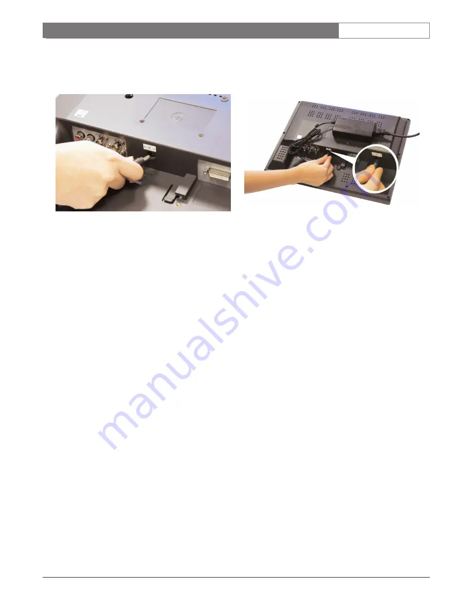
b.  Connect the other end of the extension cable

(small connector) to the power input
connector on the rear side of the LCD panel,
as shown below in Photo E.

Photo E

3. Connect the appropriate ends of the IEC power

cord to the power source (mains) and power
supply/base unit. Toggle the power switch on
the base to the ON position.

6.3.3 MON151PS Power Supply Installation

Use the MON151PS Power Supply (purchased
separately) to power the MON152CL30 unit's LCD
panel separately from the power supply/base unit. The
power source (mains) (120/230 VAC) can be located at
a distance of up to 3 m (10 ft) away. Use for a wall
mount or rack mount installation.

1. Follow the instructions in Section 6.3.1, Step 1

to remove the power supply/base from the LCD
panel section. 

NOTE: The power supply/base unit may now be
stored, as it is no longer required to power the unit.

2. Connect the bayonet connector from the power

supply to the power input connector on the rear
side of the LCD panel, as shown below in
Photo F. 

Photo F

3. Connect the IEC power cord to the

MON151PS power supply unit.  

4. Mount the LCD panel in its intended location.

5. Connect the power end of the IEC power cord

to the power supply source.

6.4

Connecting the Composite Video 
Signal to the Monitor 

There are two (2) BNC connectors located on the rear
of the monitor for composite video input and two (2)
BNC connectors for composite video outputs 
(Figure 6).

NOTE: All video inputs are active loop-through. The
impedance is automatically set to 75 ohm by the input
of the signal on the input connector, while operating in
a single connection mode (Figure 8). If a cable is also
connected to the output connector, the video signal
can be passed on to another monitor connected to it
via the active loop-through function. Up to three (3)
monitors may be connected in this manner (Figure 9).

NOTE: To select between VIDEO1 and VIDEO2,
press 

Input

(Figure 1, Item 1) located on the front of

the monitor.

MON152CL30 | 

Instruction Manual

Installation

Bosch Security Systems | April 12, 2006

Summary of Contents for MON152CL30

Page 1: ...Instruction Manual EN 15 inch Color LCD Flat Panel Display Monitor MON152CL30 ...

Page 2: ...ctrical shock or other hazards 9 Safety Check Upon completion of servicing or repairs to the unit ask the service technician to perform safety checks to ensure proper operating condition 10 Power Sources Operate the unit only from the type of power source indicated on the label If unsure of the type of power supply to use contact your dealer or local power company For units intended to operate fro...

Page 3: ...nded to operate with 230VAC 50Hz the input and output power cord must comply with the latest versions of IEC Publication 227 or IEC Publication 245 Power supply cords should be routed so they are not likely to be walked on or pinched Pay particular attention to location of cords and plugs convenience receptacles and the point of exit from the appliance 4 Overloading Do not overload outlets and ext...

Page 4: ...iempre que el cable de alimentación esté conectado a la fuente de alimentación Sin embargo la unidad sólo funciona cuando el interruptor está en la posición de encendido El cable de alimentación es la principal fuente de desconexión de todas las unidades PRECAUCIÓN PARA DISMINUIR EL RIESGO DE DESCARGA ELÉCTRICA NO RETIRE LA CUBIERTA NI LA PARTE POSTERIOR NO EXISTEN PIEZAS DE RECAMBIO EN EL INTERIO...

Page 5: ...zione costituisce il dispositivo di scollegamento dell alimentazione principale per tutte le unità ATTENZIONE PER RIDURRE IL RISCHIO DI SCOSSE ELETTRICHE NON RIMUOVERE LA COPERTURA O IL PANNELLO POSTERIORE L UNITÀ NON CONTIENE COMPONENTI INTERNI RIPARABILI DALL UTENTE PER QUALSIASI INTERVENTO RIVOLGERSI A PERSONALE TECNICO QUALIFICATO Questo simbolo indica la presenza di tensione pericolosa non is...

Page 6: ...nal to the Monitor 10 6 5 Connecting the Y C S video Signal to the Monitor 11 6 6 Connecting Audio to the Monitor 11 6 7 Connecting the DVI Signal to the Monitor 11 6 8 Ventilation 11 7 0 OPERATION 13 7 1 Front Panel Controls 13 7 2 Front Panel Lock out Feature 13 7 3 On screen Display OSD Menu Multilanguage 13 8 0 SPECIAL FEATURES 15 8 1 Channel Title 15 8 2 Underscan 15 8 3 Picture in Picture PI...

Page 7: ... For additional information see www boschsecurity com 3 0 MON152CL30 EXPLODED VIEW The front panel of the MON152CL30 contains various push button features see Figure 1 Items 1 8 that allow you to adjust your screen to different levels The back panel contains various connector openings Qty Item 1 MON152CL30 Color LCD flat panel monitor 2 Power Cords 3 wire with grounded plug 1 8 m 6 ft long One 1 w...

Page 8: ...hance the multi input capability Picture in Picture allows any of the composite video or S video inputs to be inserted into each other or into the VGA DVI I display Monitor control functions are accessed via the front panel push buttons and the multi language On screen Display OSD See Figure 1 for front panel descriptions 6 0 INSTALLATION 6 1 Power Model Rated Voltage Power Sync No Voltage Range a...

Page 9: ...re 4 Item 1 from the panel see Photo B while sliding the base off the monitor Photo B 2 Mount the unit to the mounting bracket not provided using the four 4 mounting holes on the rear panel The square mounting hole patterns are standard on 75 mm 2 9 in centers as shown in Photo C Photo C 6 3 2 Extension Cable Installation Use the Extension Cable included with the MON152CL30 to place the power supp...

Page 10: ...ply to the power input connector on the rear side of the LCD panel as shown below in Photo F Photo F 3 Connect the IEC power cord to the MON151PS power supply unit 4 Mount the LCD panel in its intended location 5 Connect the power end of the IEC power cord to the power supply source 6 4 Connecting the Composite Video Signal to the Monitor There are two 2 BNC connectors located on the rear of the m...

Page 11: ...Figure 6 Connectors Exploded View 6 7 Connecting the VGA DVI I Signal to the Monitor 6 7 1 VGA Signal Connect the analog VGA signal using the provided VGA cable DVI I to D SUB 6 7 2 DVI I Signal Connect the digital DVI I signal using a standard DVI I cable not provided Figure 7 VGA DVI I Input 6 8 Ventilation To prevent overheating ensure that the ventilation openings on the rear of the monitor ar...

Page 12: ...onitor Configuration Bosch Security Systems April 12 2006 Video Camera VCR Y C PC IN DC12V IN IN OUT AUDIO VIDEO R L Video Camera FromVideo Output Y C PC IN Y C PC IN Y C PC IN IN OUT AUDIO VIDEO R L DC12V IN IN OUT AUDIO VIDEO R L IN OUT AUDIO VIDEO R L DC12V IN DC12V IN Call Out eps IN OUT AUDIO VIDEO R L ...

Page 13: ...alue 3 Press Menu to save changes LED Indicator Indicates power is on green standby amber sleep mode flashing amber Green Power Button Press this button to power ON OFF 7 2 Front Panel Lock out Feature To lock the front panel press and hold the buttons simultaneously until a message flashes KEY LOCKED then release To unlock the front panel press and hold the buttons simultaneously until a message ...

Page 14: ...s removed from the display after 15 seconds if no selections or adjustments are made Main Menu Function Tint Adjusts tint level for best results adjust until skin color is natural NOTE Applicable to NTSC only not available in PAL format Color Adjusts the overall color intensity of the screen Default Resets to the factory default settings for brightness contrast tint color and volume Language Selec...

Page 15: ...compared to the main window causes a difference in sharpness and color PIP PAP and Channel Title can not be combined Only one can be enabled at a time EXIT CHANNEL TITLE DISABLE CHANNEL TITLE TITLE EDITING Main Menu Function Title Editing Edits the 16 character title for VIDEO1 VIDEO2 and S video Channel Title Enables disables channel title Main Menu Function PIP Input Selects composite or S video...

Page 16: ...n Off Front Panel Lockout Multiple push button combination On screen Display Video Tint NTSC only Color Default Language Channel Title Underscan PIP Menu Power on Options Volume Exit VGA DVI Auto Set Display Setting Color Temperature Language Volume Default PIP Menu Power on Options Information Exit Indicators LED Power On green Standby amber Sleep Mode flashing amber On Screen No Signal flashing ...

Page 17: ...TING VIDEO 1 VIDEO 1 EXIT CHANNEL TITLE TITLE EDITING 50 100 0 50 100 TINT COLOR LANGUAGE CHANNEL TITLE UNDER SCAN DISABLE PIP MENU VOLUME POWER ON OPTIONS EXIT DEFAULT RGB RGB TINT COLOR LANGUAGE CHANNEL TITLE UNDER SCAN DISABLE PIP MENU VOLUME POWER ON OPTIONS EXIT DEFAULT RGB RGB TINT COLOR LANGUAGE CHANNEL TITLE UNDER SCAN DISABLE PIP MENU VOLUME POWER ON OPTIONS EXIT DEFAULT RGB RGB TINT COLO...

Page 18: ...OP RIGHT BOTTOM RIGHT BOTTOM LEFT EXIT PIP LOCATION TOP LEFT PIP H POSITION PIP V POSITION PIP LOCATION PIP SIZE PIP DISABLE EXIT PIP MENU PIP INPUT TINT COLOR LANGUAGE CHANNEL TITLE UNDER SCAN DISABLE PIP MENU VOLUME POWER ON OPTIONS EXIT DEFAULT RGB RGB PAP DISABLE HV KEYSTONE TOP RIGHT BOTTOM RIGHT BOTTOM LEFT EXIT PIP LOCATION TOP LEFT PIP H POSITION PIP V POSITION PIP V POSITION 0 PIP LOCATIO...

Page 19: ...SABLE HV KEYSTONE PIP LOCATION PIP SIZE PIP DISABLE EXIT PIP MENU PIP INPUT TINT COLOR LANGUAGE CHANNEL TITLE UNDER SCAN DISABLE PIP MENU VOLUME POWER ON OPTIONS EXIT DEFAULT RGB RGB PAP DISABLE HV KEYSTONE 0 TINT COLOR LANGUAGE CHANNEL TITLE UNDER SCAN DISABLE PIP MENU VOLUME POWER ON OPTIONS EXIT DEFAULT RGB RGB TINT COLOR LANGUAGE CHANNEL TITLE UNDER SCAN DISABLE PIP MENU VOLUME POWER ON OPTION...

Page 20: ...FORMATION EXIT COLOR TEMPERATURE AUTO AUTO RGB RGB RGB RGB i 6500K 9300K EXIT COLOR TEMPERATURE EXIT 0 200 400 0 50 400 AUTO SET DISPLAY SETTING LANGUAGE VOLUME DEFAULT PIP MENU POWER ON OPTIONS INFORMATION EXIT COLOR TEMPERATURE AUTO AUTO RGB RGB i H POSTION V POSITION FINE TUNE EXIT DISPLAY SETTING H POSITION 0 50 400 AUTO SET DISPLAY SETTING LANGUAGE VOLUME DEFAULT PIP MENU POWER ON OPTIONS INF...

Page 21: ...S INFORMATION EXIT COLOR TEMPERATURE AUTO AUTO RGB RGB i AUTO SET DISPLAY SETTING LANGUAGE VOLUME DEFAULT PIP MENU POWER ON OPTIONS INFORMATION EXIT COLOR TEMPERATURE AUTO AUTO RGB RGB i VOLUME 0 100 PIP LOCATION PIP SIZE PIP DISABLE EXIT PIP MENU PIP INPUT PAP DISABLE HV KEYSTONE PIP LOCATION PIP SIZE PIP DISABLE EXIT PIP MENU PIP INPUT PAP DISABLE HV KEYSTONE VIDEO 1 VIDEO 2 S VIDEO EXIT PIP INP...

Page 22: ...ORMATION EXIT COLOR TEMPERATURE AUTO AUTO RGB RGB i PIP LOCATION PIP SIZE PIP DISABLE EXIT PIP MENU PIP INPUT PAP DISABLE HV KEYSTONE PIP LOCATION PIP SIZE PIP DISABLE EXIT PIP MENU PIP INPUT PAP DISABLE HV KEYSTONE PIP LOCATION PIP SIZE PIP DISABLE EXIT PIP MENU PIP INPUT PAP DISABLE HV KEYSTONE MEDIUM LARGE EXIT PIP SIZE SMALL PIP LOCATION PIP SIZE PIP DISABLE EXIT PIP MENU PIP INPUT PAP DISABLE...

Page 23: ...EN 23 MON152CL30 Instruction Manual Bosch Security Systems April 12 2006 ...

Page 24: ...6 security sales us bosch com http www boschsecurity us Europe Middle East Africa Bosch Security Systems B V P O Box 80002 5600 JB Eindhoven The Netherlands Phone 31 0 40 27 83955 Fax 31 0 40 27 86668 emea securitysystems bosch com http www boschsecurity com Asia Pacific Bosch Security Systems Pte Ltd 38C Jalan Pemimpin Singapore 577180 Phone 65 6319 3450 Fax 65 6319 3499 apr securitysystems bosch...

Reviews: