


14
|
Sequence of Operation
LM CS Series Heat Pump
LM CS Series Heat Pump
8 733 920 847 (2014/01)
Subject to change without prior notice
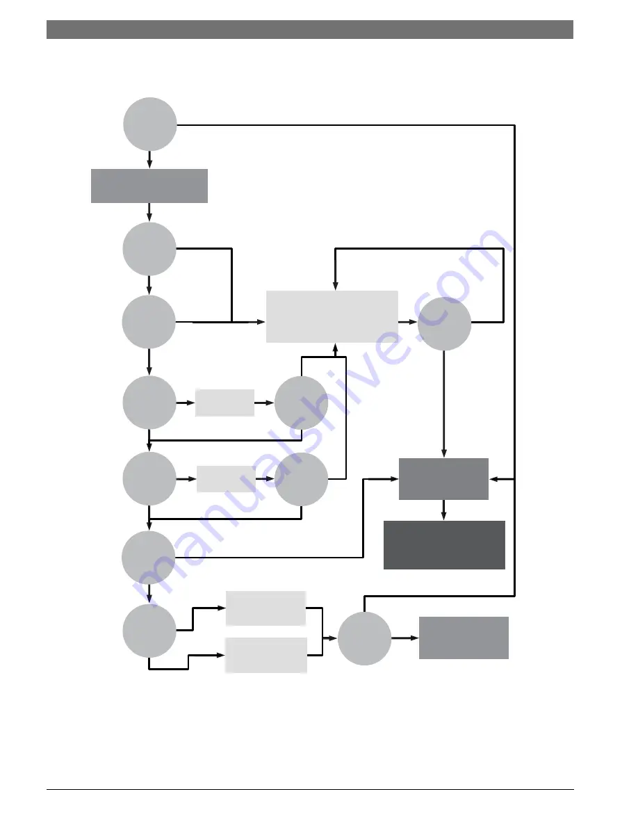
Figure # 12
UPM Sequence of Operation (SOO) Flow Chart
YES
YES
YES
YES
YES
YES
YES
YES
YES
YES
YES
NO
NO
NO
NO
NO
NO
NO
NO
NO
NO
NO
Y1=1
V
>
18VAC
HPC = 1
LPC = 1
FRZ
>
TEMP
LIM
CON
>
0
INITIAL
POWER UP
T
>
ASC OR
RS SEC
TIME
>
30
SEC
TIME
>
120
SEC
COUNT = 2
Start Timer
Start Timer
CC Output = On
CC Output = Off
Blink Code On Status LED
Report Alarm Fault
Hard Lockout
ALR Output = On/Pulse
Blink Code On Status LED
Soft Lockout
Record Alarm
Start Counter (If Applicable)
Start
Anti Short Cycle
Start
Random Start Up
Lockout Can Be Set To
4 Via Dip Switch
Power/Switchs/Sensor
Status Check
LEGEND:
HPC - HIGH PRESSURE CUTOUT
LPC - LOW PRESSURE CUTOUT
FRZ - FREEZE PROTECTION CONDITION
CON - CONDENSATE OVERFLOW CONDITION
CC - COMPRESSOR COIL
ASC - ANTI SHORT CYCLE
RS - RANDDOM START


