background image

VARI-directional array

Configuring the VARI | en

29

Bosch Security Systems B.V.

Installation manual

2018.06 | V1.3 |

6

Configuring the VARI

This section describes how to use the VARI-control software to create a data file - the
configuration file - specific to the loudspeaker being installed.
The VARI-control software can be downloaded from the Bosch Product Website:
www.boschsecurity.com.
The electronics section within the VARI base unit is very sophisticated and controls all aspects
of the VARI unit’s operation. The configuration file which is created in VARI-control and
uploaded to the line array not only specifies how the unit will perform acoustically, for
example, volume, coverage angles, equalization, etc., but also incorporates data specifying
how the unit should operate under certain emergency conditions, what circumstances
constitute a “reportable” failure, and so on. VARI-control requires the installer to enter various
dimensional data concerning the loudspeaker’s location and its intended area of coverage. The
file subsequently created is then uploaded from the PC to the loudspeaker via the RS‑485
network connection.

6.1

Installation of VARI-control software on a PC

These notes describe how to install the VARI-control software application on a PC running
Windows. If the user is unfamiliar with VARI-control he/she is strongly advised, after installing
the application, to study the various “Help files” before attempting to use any of its functions
beyond the basic unit configuration described elsewhere in this manual.
To download the VARI-control software:
1.

Go to: www.boschsecurity.com and select the 

Product Catalog

.

2.

Choose your country.

3.

Click 

Public Address and Voice Alarm

Loudspeakers

VARI-directional array

Product

Page

.

4.

Select the tab: 

Software & Support

.

6.1.1

Minimum PC requirements

Processor/Storage

Pentium III, 1


GHz, 256


MB RAM, 500


MB (min.) of free disk space.

Operating System

Windows 7 or 10.

Ports

One free USB port.

6.1.2

Administrator

The installation and registration of VariControl requires Administrator rights. It is possible to
run VariControl as a user with limited access rights.

Summary of Contents for LA3-VARI-CM

Page 1: ...VARI directional array LA3 VARI B LA3 VARI BH LA3 VARI E LA3 VARI CM LA3 VARI CS en Installation manual ...

Page 2: ......

Page 3: ...tional CobraNet module 19 4 5 Mechanical installation 20 4 5 1 Mounting height 20 4 5 2 Flush mounting 20 4 5 3 Mounting the loudspeaker 20 5 Connector and wiring details 23 5 1 AC Mains input 1 24 5 2 Backup DC power supply input 2 24 5 3 Line level input 1 4 and 2 5 25 5 4 100 V input 1 6 and 2 7 25 5 5 RS 485 network in 8 and thru 9 26 5 5 1 Network configuration 26 5 5 2 Cable length 27 5 5 3 ...

Page 4: ...4 en Table of contents VARI directional array 2018 06 V1 3 Installation manual Bosch Security Systems B V 6 4 5 Loading a previously saved settings file 36 7 Technical Data 38 ...

Page 5: ... such an alert is not being observed 1 1 Reference to EC statement of conformity This document confirms that products bearing the CE label meet all the requirements in the EMC directive 2004 108 EC and LV directive 2006 95 EC laid down by the Member States Council for adjustment of legal requirements Furthermore the products comply with the rules and regulations from 30 August 1995 referring to th...

Page 6: ... information provided in these instructions In no event shall Bosch Security Systems B V be liable for any special indirect or consequential damages whatsoever resulting from loss of use data or profits whether in action of contract negligence or other tortious action arising out of or in connection with the use of the information provided in these Installation and User Instructions No part of thi...

Page 7: ...figurations mounted at 3 m above floor level Distance VARI B VARI B E VARI B E E VARI BH VARI BH E VARI BH E E 20 m 90 dBA 89 dBA 32 m 90 dBA 89 dBA 50 m 88 dBA 87 dBA VARI BH base units employ co axial drivers instead of the single coil drivers fitted to the VARI B These give the line arrays an extended high frequency response and this model is better suited to applications where the audio system...

Page 8: ...8 en System Overview VARI directional array 2018 06 V1 3 Installation manual Bosch Security Systems B V Figure 3 1 VARI overview grilles removed for identification ...

Page 9: ...ded VARI CobraNet Module VARI base units may be fitted with an optional CobraNet input module CobraNet is a proprietary audio network protocol used widely in large infrastructures to carry multiple channels of digital audio and other control data bi directionally over Ethernet using CAT 5 cable The VARI CM module allows VARI line arrays to be directly interfaced to a CobraNet network Notice Note t...

Page 10: ...1 Phoenix connector 2 pole 7 62 mm pitch DC power input 2 Hinged mounting bracket Wall mounting 4 30 mm hex headed screws with washers and wall plugs Fixings for wall mounting 1 Grille removal tool Removal of front protective grille In addition to the line array itself each VARI E extension unit is shipped with the following items Qty Item Use 2 M5 x 12 mm hex headed bolts Secure Extension to base...

Page 11: ... for installation Before starting to install the VARI loudspeaker a number of points should be considered Mounting location VARI loudspeakers are designed to be mounted on a vertical surface e g a wall or column If the vertical axis is tilted such that the loudspeaker is pointing up or down even a few degrees the effective sound coverage will be considerably impaired Thus when choosing a location ...

Page 12: ...t he she is aware of the precise local requirements in this respect It may be necessary to provide a separate mains distribution network or an uninterruptible mains power supply UPS 4 2 Power Signal and Control cables Since VARI loudspeakers will frequently be installed in locations which are difficult to access readily consideration should be given to the cables required at each mounting position...

Page 13: ...s supply For ease of installation the VARI base unit is delivered with a rewireable angled IEC mains power cable connector Only this connector may be used and should be fitted to a power cord of the required length Refer to section Connector and wiring details page 23 4 2 2 Audio inputs The VARI base unit provides two input channels that accept audio signals at either line level 0 dBV or from a 10...

Page 14: ...Refer to section External control input 10 page 28 for wiring details 4 2 6 RS 485 network The VARI s RS 485 connection is primarily the method by which it gets configured using the VariControl software application The unit s configuration file will generally be loaded before mechanical installation using the cable supplied with the VARI CS Configuration Set Additionally continuous monitoring of t...

Page 15: ...to prevent RF emission from the internal high speed digital circuits this protection will not work properly if the chassis is not connected to ground RF Immunity RF currents induced in the signal cables by external RF fields are effectively shorted to chassis ground provided that the cable screen shield is of sufficiently low impedance In addition to the mains ground the VARI B BH connector block ...

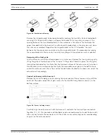
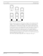
Page 16: ...guration of the VARI directional Line Array is one base unit plus two extension units Do not attempt to add additional extension units 4 3 1 Attachment method On a clear clean and flat floor area lay the VARI B or VARI BH base unit down on its back face up In the top surface of the enclosure observe two tapped holes M5 and a small plate secured by two screws Remove the plate and retain it a recess...

Page 17: ...own in a similar way Remove the front grille by gently lifting the grille at the locations of the snap on fittings which hold it in place Use the grille removal tool provided for this Note that the two end surfaces of the extension unit also have two M5 holes and a multipin connector Note the removable cover panel in the baffle at one end of the extension unit this is the end that needs to be atta...

Page 18: ...ith a spanner If a second extension unit is to be attached to the first repeat the procedure The holes in the top surface of the extension units have M5 inserts in the same way as base units and the method of attaching two extensions together is identical to that already described for attaching an extension unit to a base unit Replace the access compartment cover panel s in the front baffle s of t...

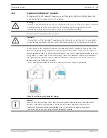
Page 19: ...ion of the module To install access the CobraNet module see following figure remove the front grille of the base unit by gently lifting the grille at the locations of the snap on fittings which hold it in place and remove the 12 screws of the cover plate Take out the cover plate module by gently lifting and turn it over take care of the wiring Place the CobraNet module as indicated in the figure f...

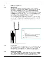
Page 20: ...onfiguration software allows the bottom of the base unit to be between 0 and 3 5 m above ear level If the intended ear level is e g 1 7 m for people standing the bottom of the base unit must be at a height of 1 7 to 5 2 m above the floor VARI units must only ever be installed with the base unit s connector bay at the bottom of the assembly never upside down Figure 4 7 Mounting height 4 5 2 Flush m...

Page 21: ...e 80 mm above this Mark the other pairs of holes higher up the centreline using the dimensions given in the drawing Note that the hole spacing for the two holes in each bracket is always 80 mm 3 Mark and drill the holes 8 mm for the wall plugs 4 Insert the plugs and screws into the holes Tighten the screws with a spanner but stop with a few mm of screw shaft visible between the head and the wall 5...

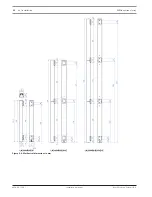
Page 22: ...22 en Installation VARI directional array 2018 06 V1 3 Installation manual Bosch Security Systems B V Figure 4 8 Mechanical dimensions in mm ...

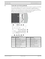
Page 23: ...screw terminal connectors All mating connectors are supplied note that three different sizes are used All connectors on the VARI have male contacts The pinouts of each connector are given in the next paragraphs Figure 5 1 Base unit connectors Figure 5 2 Base unit connector overview Reference Connector Reference Connector 1 AC mains input 7 Input 2 100 V 2 Backup DC power supply input 8 RS 485 netw...

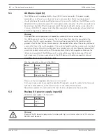
Page 24: ... unit which causes a live conductor to contact the casing will cause a current to flow in the earth conductor This current should trip either an externally installed overcurrent device fuse or circuit breaker or a residual current circuit breaker ground fault circuit interrupter which will cut off the supply of electricity to the appliance Because the IEC mains connector of the VARI base unit is n...

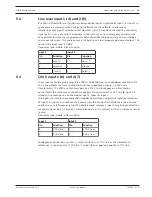
Page 25: ...ts should only be used if the VARI is to be fed from an audio power amplifier with 100 V line outputs or from an amplifier with low impedance outputs via 100 V line transformers The VARI can thus form part of a 100 V line loudspeaker system and be connected in the same way as the other speakers Do not connect a 100 V line to input 1 if already a line level input is connected to input 1 Idem for in...

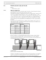
Page 26: ...S 485 network the thru connector 9 can be ignored The pinout of the two RS 485 connectors is identical They should be wired as shown in the table and diagram below using cable with two separate twisted pairs with individual screens Connector type 5 pole 3 81 mm pitch RS 485 in RS 485 thru Pin Function Pin Function 1 Ground 6 Ground 2 Data Tx Y 7 Data Tx Y 3 Data Tx Z 8 Data Tx Z 4 Data Rx B 9 Data...

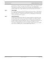
Page 27: ...sed With good quality cable a safe maximum figure is 2000 m If the distance is significantly longer than this a network repeater will be required Refer to section RS 485 network page 14 5 5 3 Cable termination According to the official RS 485 standard the network should be terminated with 120 ohm resistors at both ends of each pair while the length of the stub lines should not exceed 7 m The RS 48...

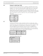
Page 28: ...l Connector type 3 pole 3 81 mm pitch Pin Function 4 n c 5 VDC 6 VDC 5 7 Failure relay 11 If continuous monitoring of the VARI via the RS 485 network is not implemented a simple monitoring function can be realised with the Failure relay This has two NC Normally Closed contacts which open when a fault condition arises The definition of fault condition in this context is programmed by the VariContro...

Page 29: ...e loudspeaker s location and its intended area of coverage The file subsequently created is then uploaded from the PC to the loudspeaker via the RS 485 network connection 6 1 Installation of VARI control software on a PC These notes describe how to install the VARI control software application on a PC running Windows If the user is unfamiliar with VARI control he she is strongly advised after inst...

Page 30: ...ta for all VARI array configurations There are two setup executables for the VARI the first one installs the data for the VARI B VARI B E and VARI B E E The second setup executable installs the data for the VARI BH VARI BH E and VARI BH E E These libraries are installed as programs to be able to manage the default destination folders of the libraries and automatically clean up old libraries in cas...

Page 31: ...ge 23 The interface has two connectors One is a USB connector which is connected to a USB port on the PC using the short USB cable supplied The other is a 5 pin Phoenix connector which should be connected to the RS 485 Network Connection input on the VARI base unit refer to section RS 485 network in 8 and thru 9 page 26 using the 5 m long Phoenix to Phoenix cable also supplied The VARI loudspeaker...

Page 32: ...the converter is connected If a CobraNet module has been installed the CobraNet serial bridge can be selected as communication port for configuration via Ethernet Figure 6 3 VariControl Communication options VariControl auto detects the VARI configuration to which it is connected and the precise appearance of the opening screen will reflect the particular model s By double clicking a particular un...

Page 33: ... time to reflect the values of the physical parameters Two versions of the Results display are available selected by the two buttons above the diagram Coverage shows an on axis vertical cross section through the sound field On axis means that the cross section is perpendicular to the vertical centre line of the array The loudspeaker position is on the left hand vertical axis the vertical line repr...

Page 34: ...ld be left at 0 0 m if the audience area is horizontal Many venues use raked seating however and if this is the case the height of the last row of the seating should be entered here Rise is adjustable in increments of 0 1 m Ear level Listening height The height of the audience s ears above floor level will be greater in a standing venue than one with seats and this parameter may be adjusted to all...

Page 35: ...evels EQ In 1 Each input has a 4 band equalisation available with a choice of fully parametric hi pass low pass notch bell or shelving filters in each band Gain delay In 2 As for Input 1 EQ In 2 As for Input 1 Volume Provides adjustment of overall unit volume Controls for setting gain in the analog domain both before Analog pre gain and after Analog output gain the DSP section are included Volume ...

Page 36: ...fault ini Installers will generally wish to save the settings file s in a different location clicking on the folder symbol to the right of the File name box will open a standard Save As window Navigate to the desired location and give the file a name Click Save Note that VARI settings files have a ini filename extension 4 Click OK If the filename in the File name box has not been changed a Warning...

Page 37: ...ns box in the Presets pane 4 The File name box in the Settings file pane specifies the location of the settings file to be loaded Clicking on the folder symbol to the right of the File name box will open a standard Open window Navigate to the folder containing the desired file click on the file and then click Open 5 Click OK An Info dialogue box appears confirming the file saving details Click OK ...

Page 38: ... 130 Hz to 18 kHz 3 dB Max SPL3 Continuous peak VARI B 90 93 dB SPL A weighed at 20 m VARI B E 90 93 dB SPL A weighed at 32 m VARI B E E 88 91 dB SPL A weighed at 50 m VARI BH 89 92 dB SPL A weighed at 20 m VARI BH E 89 92 dB SPL A weighed at 32 m VARI BH E E 87 90 dB SPL A weighed at 50 m Coverage Horizontal fixed 4 130 6 dB avg 1 to 4 kHz Vertical adjustable 5 Software configurable Maximum throw...

Page 39: ...e balanced 1 Mohm at 1 kHz Power Amplifiers Power VARI B H 8 x 15 W class D full bridge VARI E 4 x 25 W class D full bridge Protection Thermal shutdown Current limiting Dynamic range6 105 dB PSU Mains voltage 100 to 120 V 200 to 240 V auto switching Power consumption Mains 24 Vdc 22 V min 36 V max Power save VARI B H 13 4 5 W VARI B H E 17 7 W VARI B H E E 19 9 W Idle VARI B H 18 8 5 W VARI B H E ...

Page 40: ...ensation filtering Compressor Volume AVC Control Network interface RS 485 full duplex auto switching 115k2 57k6 38k4 19k2 baud optically isolated Max number of units7 126 Surveillance General status Amplifier and load monitoring External pilot tone detection 20 kHz to 30 kHz min level 22 dBV Built in ambient noise sensing microphone Thermal overload protection Failure relay Maskable conditions Con...

Page 41: ... x 130 x 98 mm 94 5 x 5 1 x 3 8 in VARI B H E E 3600 x 130 x 98 mm 141 7 x 5 1 x 3 8 in Bracket 27 mm 1 1 in additional depth flat mounted VARI CM 100 x 50 x 23 mm 3 9 x 2 0 x 0 9 in Weight VARI B H 13 0 kg 28 7 lbs VARI B H E 24 7 kg 54 5 lbs VARI B H E E 36 4 kg 80 3 lbs Color Enclosure VARI B H and E RAL9007 gray aluminum Grill VARI B H and E RAL9006 white aluminum Environmental Operating tempe...

Page 42: ...s depending on the actual signal processing parameters and air absorption at larger distances A typical bandwidth is specified for the complete array under full space radiation conditions 3 Levels are valid for pink noise 100 Hz to 20 kHz bandwidth with a crest factor of 3 dB default EQ and minimum opening angle setting Continuous is the RMS level Peak is the absolute peak level both determined at...

Page 43: ......

Page 44: ...Bosch Security Systems B V Torenallee 49 5617 BA Eindhoven Netherlands www boschsecurity com Bosch Security Systems B V 2018 ...

Reviews: