background image

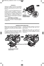
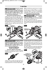
CALIBRE DE PROFUNDIDAD

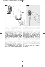
La  profundidad  de  perforación  se  puede  prefijar  y/o
repetir utilizando el calibre de profundidad.

Ajuste de la profundidad:  Después de instalar el mango
auxiliar,  asegúrese  de  que  el  accesorio  se  haya
introducido  completamente  en  el  portaherramienta
antes de ajustar el calibre de profundidad (Fig. 8).

Para  ajustar  la  profundidad,  oprima  el  botón  de
liberación  del  calibre  de  profundidad,  deslice  dicho
calibre  hasta  la  profundidad  deseada  y  deje  de  ejercer
presión  sobre  el  botón  para  fijar  el  calibre  de
profundidad en su sitio.

X

MANGO AUXILIAR

La herramienta se debe sujetar con el mango auxiliar, el
cual se puede girar 360°.

Para    reposicionar  y/o  hacer  girar  el  mango,  afloje  la
empuñadura,  mueva  el  mango  hasta  la  posición
deseada  a  lo  largo  del  cuerpo  cilíndrico  y  vuelva  a
apretar firmemente la empuñadura (Fig. 7).

1

2

3

-38-

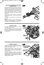
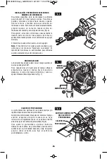
INSTALACIÓN Y REMOCIÓN DE ACCESORIOS

MANDRIL DE 3 MORDAZAS

Para  brocas  pequeñas,  abra  las  mordazas  lo  suficiente
para  in troducir  la  broca  hasta  las  estrías.  Para  brocas
grandes,  in tro duzca  la  broca  hasta  donde  se  pueda.
Centre  la  broca  a  me dida  que  vaya  cerrando  las
mordazas a mano. Esto co lo ca la broca adecuadamente,
proporcionando  un  contacto  má x i mo  entre  las
mordazas del mandril y el cuerpo de la bro ca (Fig. 6).

Para  apretar  el  mandril,  introduzca  sucesivamente  la
llave  en  cada  uno  de  los  tres  agujeros  para  llave  y
apriete firmemente girando en el sentido de las agujas
del reloj.

El mandril se puede soltar usando un solo agujero.

Nota:

El  mandril  de  3  mordazas  está  diseñado  para

utilizarse  en  el  modo  de  "Taladrado  solamente".  El
mandril de 3 mordazas no está diseñado para utilizarse
cuando se taladre con acción de percusión.

2

FIG. 6

MANGO

AUXILIAR

CALIBRE DE

PROFUNDIDAD

BOTÓN DE LIBERACION

DEL CALIBRE DE

PROFUNDIDAD

FIG. 7

FIG. 8

EMPUNADURA

2610048709.qxp_GBH18V-20  6/19/17  12:42 PM  Page 38

Summary of Contents for GBH18V-20

Page 1: ... fonctionnement sécurité Instrucciones de funcionamiento y seguridad 1 877 BOSCH99 1 877 267 2499 www boschtools com Call Toll Free for Consumer Information Service Locations Pour obtenir des informations et les adresses de nos centres de service après vente appelez ce numéro gratuit Llame gratis para obtener información para el consumidor y ubicaciones de servicio GBH18V 20 2610048709 qxp_GBH18V ...

Page 2: ...a damp location is unavoidable use a Ground Fault Circuit Interrupter GFCI protected supply Use of an GFCI reduces the risk of electric shock Personal safety Stay alert watch what you are doing and use common sense when operating a power tool Do not use a power tool while you are tired or under the influence of drugs alcohol or medication A moment of inattention while operating power tools may res...

Page 3: ...ntally Store idle power tools out of the reach of children and do not allow persons unfamiliar with the power tool or these instructions to operate the power tool Power tools are dangerous in the hands of untrained users Maintain power tools Check for misalignment or binding of moving parts breakage of parts and any other condition that may affect the power tool s operation If damaged have the pow...

Page 4: ... preventive safety measures reduce the risk of starting the tool accidentally Position yourself to avoid being caught between the tool or side handle and walls or posts Should the bit become bound or jammed in the work the reaction torque of the tool could crush your hand or leg If the bit becomes bound in the workpiece release the trigger immediately reverse the direction of rotation and slowly s...

Page 5: ...ine carbon tetrachloride ammonia etc may damage plastic parts Ensure the switch is in the off position before inserting battery pack Inserting the battery pack into power tools that have the switch on invites accidents Some dust created by power sanding sawing grinding drilling and other construction activities contains chemicals known to cause cancer birth defects or other reproductive harm Some ...

Page 6: ...tainable speed min Revolutions or reciprocation per minute revolutions strokes surface speed orbits etc per minute 0 Off position zero speed zero torque 1 2 3 I II III Selector settings speed torque or position settings Higher number means greater speed 0 Infinitely variable selector with off speed is increasing from 0 setting Arrow action in the direction of arrow Alternating current type or a ch...

Page 7: ...boratories This symbol designates that this component is recognized by Underwriters Laboratories This symbol designates that this tool is listed by Underwriters Laboratories to United States and Canadian Standards This symbol designates that this tool is listed by the Canadian Standards Association This symbol designates that this tool is listed by the Canadian Standards Association to United Stat...

Page 8: ...f starting the tool accidentally Cordless Hammer Drill DUST SHIELD LOCKING SLEEVE BATTERY PACK VARIABLE SPEED CONTROLLED TRIGGER SWITCH FORWARD REVERSING LEVER AND TRIGGER LOCK MODE SELECTOR DIAL LED LIGHT RUBBERIZED GRIP VENTILATION OPENINGS DEPTH GAUGE RELEASE BUTTON HAND GRIP AUXILIARY HANDLE BATTERY PACK RELEASE BUTTON DEPTH GAUGE FIG 1 Battery Packs Chargers Please refer to the Charger Manual...

Page 9: ...ves or cloth to remove To remove an accessory pull locking sleeve backward and pull bit forward All accessories should be wiped clean after removing Fig 3 1 2 3 2 1 FIG 2 FIG 3 DUST SHIELD LOCKING SLEEVE Assembly Disconnect battery pack from tool or place the switch in the locked or off position before making any assembly adjustments or changing accessories Such preventive safety measures reduce t...

Page 10: ...6 AUXILIARY HANDLE The tool must be supported with the auxiliary handle which can be swiveled 360 To reposition and or swivel the handle loosen the hand grip move the handle to the desired position along the barrel and securely retighten the hand grip Fig 7 1 2 3 AUXILIARY HANDLE DEPTH GAUGE Your drilling depth can be pre set and or repeated by using the depth gauge Setting depth After the auxilia...

Page 11: ...pointed away from you move the lever to the far left For reverse rotation move the lever to the far right To activate trigger lock move lever to the center off position Do not change direction of rotation until the tool comes to a complete stop Shifting during rotation of the chuck can cause damage to the tool Operating Instructions MODE SELECTOR DIAL The selector dial allows the tool to be set fo...

Page 12: ... VARIO LOCK Choose a position which is best suited for your operation The Vario Lock position is intended for use with chipping bits such as bull points spades gouges etc Depress release button and turn the selector dial to the vario lock setting Next rotate the locking sleeve along with the accessory to the desired position Then turn the selector dial to the hammer only setting and slightly turn ...

Page 13: ...reduce the pressure and continue running the drill as the bit is withdrawn Materials such as glass porcelain ceramics tiles plastics etc should be drilled at low speeds with specially designed drill bits and lubricants DRILLING WOOD OR PLASTIC If backing block is not used ease up on the pressure just before the bit breaks through the wood to avoid splintering Complete the hole from the opposite si...

Page 14: ...lable to connect the Bosch dust extraction attachment to any common size vacuum hose See Boschtools com for details Turn the dust extractor on and place the attachment 1 on the wall or the floor over the desired drilling location so that the center of the hole lines up with the center of the opening of the brush ring 2 Note the suction from the dust extractor will hold the attachment in place on t...

Page 15: ...ge the charger TOOL LUBRICATION Your Bosch tool has been properly lubricated and is ready for use D C MOTORS The motor in your tool has been engineered for many hours of dependable service To maintain peak efficiency of the motor we recommend it be examined every six months Only a genuine Bosch replacement motor specially designed for your tool should be used Cleaning To avoid accidents always dis...

Page 16: ...et réduisent le risque de choc électrique S il est absolument nécessaire d utiliser l outil électroportatif dans un endroit humide utilisez une alimentation protégée par un disjoncteur de fuite de terre GFCI L utilisation d un disjoncteur GFCI réduit les risques de choc électrique Sécurité personnelle Restez concentré faites attention à ce que vous faites et servez vous de votre bon sens lorsque v...

Page 17: ...ge changement d accessoires ou avant de ranger l outil électroportatif De telles mesures de sécurité préventive réduisent le risque de démarrage intempestif de l outil électroportatif Rangez les outils électroportatifs dont vous ne vous servez pas hors de portée des enfants et ne permettez pas à des personnes qui ne connaissent pas l outil électroportatif ou qui ignorent ces consignes de s en serv...

Page 18: ... piles de l outil avant d effectuer tout assemblage ou réglage ou de changer des accessoires Ces mesures de sécurité préventives réduisent le risque d une mise en marche accidentelle de l outil Placez vous de manière à éviter d être pris entre l outil ou la poignée latérale et les murs ou les montants Si le foret se coince ou grippe dans l ouvrage le couple de réaction de l outil pourrait écraser ...

Page 19: ...e carbone l ammoniaque etc risquent d abîmer les plastiques Veillez à ce que l interrupteur soit dans la position de fermeture avant d insérer le bloc piles L insertion d un bloc piles dans un outil électroportatif dont l interrupteur est dans la position de marche est une invite aux accidents Les travaux à la machine tel que ponçage sciage meulage perçage et autres travaux du bâtiment peuvent cré...

Page 20: ...um pouvant être atteinte min Tours ou mouvement alternatif par minute tours coups vitesse en surface orbites etc par minute 0 Position d arrêt vitesse zéro couple zéro 1 2 3 I II III Réglages du sélecteur Réglages de vitesse de couple ou de position Un nombre plus élevé signifie une vitesse plus grande 0 Sélecteur variable à l infini avec arrêt La vitesse augmente depuis le réglage 0 Flèche action...

Page 21: ...ue cet outil est approuvé par Underwriters Laboratories Ce symbole indique que ce composant est reconnu par Underwriters Laboratories Ce symbole signifie que cet outil est approuvé par Underwriters Laboratories selon les normes des États Unis et du Canada Ce symbole signifie que cet outil est approuvé par l Association canadienne de normalisation Ce symbole signifie que cet outil est approuvé par ...

Page 22: ...l FIG 1 MANCHON DE VERROUILLAGE GÂCHETTE DE COMMANDE À VITESSE VARIABLE LEVIER DE MARCHE AVANT ARRIÈRE ET VERROUILLAGE DE GÂCHETTE ÉCLAIRAGE D APPOINT INTÉGRÉ POIGNÉE CAOUTCHOUTÉE PRISES D AIR BOUTON DE BLOCAGE DE LA BUTÉE DE PROFONDEUR POIGNEE PRISE PARE POUSSIÈRE POIGNEE AUXILIAIRE BLOC PILES BOUTON DE DÉCLENCHEMENT DU BLOC PILES CADRAN DE SÉLECTION DE MODE BUTÉE DE PROFONDEUR Bloc piles chargeu...

Page 23: ...ière et tirez le embout vers l avant Essuyez tous les accessoires pour les nettoyer après les avoir enlevés Fig 3 23 Assemblage Débranchez le bloc piles de l outil ou placez l interrupteur à la position de blocage ou d arrêt avant d effectuer tout assemblage ou réglage ou de changer les accessoires Ces mesures de sécurité préventives réduisent le risque d une mise en marche accidentelle de l outil...

Page 24: ...E La poignée auxiliaire qui pivote sur 360 doit être utilisée pour supporter l outil Pour repositionner et ou faire pivoter la poignée desserrez la manette déplacez la poignée à la position désiré le long du cylindre puis resserrez fermenment la manette Fig 7 BUTÉE DE PROFONDEUR La butée de profondeur permet de pré régler la profondeur de perçage ou d effectuer des perçages répétitifs à une profon...

Page 25: ...igé en sens opposé à vous déplacez le levier à l extrême gauche Pour la rotation inverse déplacez le levier à l extrême droite Pour actionner le verrouillage de gâchette déplacez le levier à la position centrale arrêt Ne changez pas le sens de rotation avant que l outil ne se soit complètement immobilisé Un changement durant la CADRAN DE SÉLECTION DE MODE Le cadran sélecteur permet de régler l out...

Page 26: ... du bâti de l outil Fig 12 VARIO LOCK Choisissez le réglage qui convient à votre opération particulière La position Vario Lock s utilise avec les embouts de dégrossissage tels que burins vrilles gouges etc TAppuyez sur le bouton de déclenchement et tournez le cadran sélecteur au réglage vario lock Ensuite tournez à la position désirée le manchon de verrouillage ainsi que l accessoire Réglez ensuit...

Page 27: ...inue à couper Si on laisse le foret tourner tout simplement dans le trou il s émoussera rapidement Pour percer un trou de dimensions plus grandes il est plus rapide et plus facile pour votre bloc piles de pratiquer d abord un trou plus petit puis de l agrandir aux dimensions nécessaires Lubrifiez parfois la pointe du foret à l aide d HUILE DE COUPE pour faciliter le perçage des métaux Si le foret ...

Page 28: ...lacement de perçage désiré de façon que le centre du trou soit aligné sur le centre de l ouverture de la couronne à brosse 2 Remarque la force d aspiration provenant de l extracteur de poussière de l aspirateur maintiendra l attachement en place sur la surface de travail Placez la mèche dans l ouverture de la couronne à brosse à l endroit désiré pour le perçage et percez le trou désiré Fig B Dans ...

Page 29: ... outil fonctionne incorrectement GRAISSAGE DE L OUTIL Votre outil Bosch a été graissé de manière appropriée et il est prêt à l usage MOTEURS C C Le moteur de votre outil a été conçu pour de nombreuses heures d utilisation fiable Pour maintenir l efficacité maximale du moteur nous recommandons de l examiner tous les six mois Seul un moteur de remplacement Bosch authentique conçu spécialement pour v...

Page 30: ...erramientas mecánicas a la lluvia o a condiciones mojadas La entrada de agua en una herramienta mecánica aumentará el riesgo de que se produzcan sacudidas eléctricas No maltrate el cordón de energía No use nunca el cordón para transportar la herramienta mecánica tirar de ella o desenchufarla Mantenga el cordón alejado del calor el aceite los bordes afilados o las piezas móviles Los cordones dañado...

Page 31: ... seguridad reducen el riesgo de arrancar accidentalmente la herramienta mecánica Guarde las herramientas que no esté usando fuera del alcance de los niños y no deje que personas que no estén familiarizadas con la herramienta mecánica o con estas instrucciones utilicen la herramienta Las herramientas mecánicas son peligrosas en manos de usuarios que no hayan recibido capacitación Mantenga las herra...

Page 32: ...lizar cualquier ensamblaje ajuste o cambio de accesorios Dichas medidas preventivas de seguridad reducen el riesgo de arrancar la herramienta accidentalmente Sitúese de modo que evite ser atrapado entre la herramienta o el mango lateral y las paredes o los postes Si la broca se atasca o se engancha en la pieza de trabajo el par motor de reacción de la herramienta podría aplastarle la mano o la pie...

Page 33: ...oruro de carbono amoníaco etc podrían dañar las piezas de plástico Asegúrese de que el interruptor esté en la posición de apagado antes de introducir el paquete de batería Si se introduce el paquete de batería en herramientas mecánicas que tengan el interruptor en la posición de encendido se invita a que se produzcan accidentes Cierto polvo generado por el lijado aserrado amolado y taladrado mecán...

Page 34: ...oluciones o alternación por minuto revoluciones golpes velocidad de superficie órbitas etc por minuto 0 Posición off velocidad cero par motor cero 1 2 3 I II III Graduaciones del selector graduaciones de velocidad par motor o posición Un número más alto significa mayor velocidad 0 Selector infinitamente variable con apagado la velocidad aumenta desde la graduación de 0 Flecha Acción en la direcció...

Page 35: ...s Laboratories Este símbolo indica que este componente está reconocido por Underwriters Laboratories Este símbolo indica que Underwriters Laboratories ha catalogado esta herramienta indicando que cumple con las normas estadounidenses y canadienses Este símbolo indica que esta herramienta está catalogada por la Canadian Standards Association Este símbolo indica que la Canadian Standards Association...

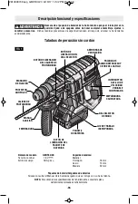
Page 36: ...LVO MANGUITO DE FIJACIÓN PAQUETE DE BATERÍAS INTERRUPTOR GATILLO DE VELOCIDAD VARIABLE CONTROLADA PALANCA DE AVANCE RETROCESO Y CIERRE DEL GATILLO DIAL SELECTOR DE MODO LUZ DE TRABAJO INCORPORADA EMPUÑADURA CAUCHUTADA ABERTURAS DE VENTILACIÓN BOTÓN DE LIBERACION DEL CALIBRE DE PROFUNDIDAD BOTÓN DE LIBERACIÓN DEL DIAL SELECTOR EMPUNADURA MANGO AUXILIAR BOTÓN DE LIBERACIÓN DEL PAQUETE DE BATERÍAS CA...

Page 37: ...ios Para quitar un accesorio tire hacia atrás del mango de fijación sujételo y tire de la broca hacia adelante Todos los accesorios deben limpiarse después de quitarlos Fig 3 37 Ensamblaje Desconecte el paquete de baterías de la herramienta o ponga el interruptor en la posición fijada o de apagado antes de hacer cualquier ensamblaje ajustes o cambiar accesorios Dichas medidas preventivas de seguri...

Page 38: ... empuñadura Fig 7 1 2 3 38 INSTALACIÓN Y REMOCIÓN DE ACCESORIOS MANDRIL DE 3 MORDAZAS Para brocas pequeñas abra las mordazas lo suficiente para introducir la broca hasta las estrías Para brocas grandes introduzca la broca hasta donde se pueda Centre la broca a medida que vaya cerrando las mordazas a mano Esto coloca la broca adecuadamente proporcionando un contacto máximo entre las mordazas del ma...

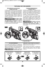
Page 39: ...to a usted mueva la palanca comple tamente hacia la izquierda Para la rotación inversa mueva la palanca completamente hacia la derecha Para activar el cierre del gatillo mueva la palanca hasta la posición central OFF No cambie el sentido de giro hasta que la herramienta se haya detenido por completo El cambio durante el giro del mandril puede causar daños a la herramienta Instrucciones de funciona...

Page 40: ...rá de girar si el accesorio se atasca y sobrecarga la herramienta 1 2 BOTÓN DE LIBERACIÓN DEL DIAL SELECTOR Ponga la palanca de avance inversión en la posición central de apagado Deslice el paquete de baterías cargado al interior de la carcasa hasta que dicho paquete se acople en su sitio Fig 12 La herramienta está equipado con un pestillo de fijación secundario para impedir que dicho paquete se c...

Page 41: ...DRADO DE METAL Realice una punzonadura para marcar en el material a fin de comenzar más fácilmente Ejerza suficiente presión para hacer que la broca siga cortando Si se permite que la broca se limite a girar en el agujero sin avanzar ésta se desafilará en poco tiempo Al taladrar un agujero más grande es más rápido y gasta menos el paquete de baterías hacer primero un agujero más pequeño y agrandar...

Page 42: ...obre la ubicación de taladrado deseada de manera que el centro del agujero se alinee con el centro de la abertura del anillo con cepillo 2 Nota la succión del extractor de polvo aspiradora sujetará el aditamento en la posición correcta sobre la superficie de trabajo Coloque la broca taladradora a través de la abertura del anillo con cepillo en la ubicación de taladrado deseada y taladre el agujero...

Page 43: ...sultado puede ser que la herramienta funcione incorrectamente o que el cargador se dañe LUBRICACION DE LAS HERRAMIENTAS Su herramienta Bosch ha sido lubricada adecuadamente y está lista para la utilización MOTORES CORRIENTE DIRECTA El motor de la herramienta ha sido diseñado para muchas horas de servicio fiable Para mantener un rendimiento óptimo del motor recomendamos que éste sea examinado cada ...

Page 44: ... À COMPTER DE LA DATE D ACHAT CERTAINS ÉTATS AMÉRICAINS CERTAINES PROVINCES CANADIENNES N ADMETTANT PAS LE PRINCIPE DE LA LIMITATION DE LA DURÉE DES GARANTIES IMPLICITES IL EST POSSIBLE QUE LES LIMITATIONS CI DESSUS NE S APPLIQUENT PAS À VOTRE CAS EN AUCUN CAS LE VENDEUR NE SAURAIT ÊTRE TENU POUR RESPONSABLE DES INCIDENTS OU DOMMAGES INDIRECTS INCLUANT MAIS NE SE LIMITANT PAS AUX PERTES DE PROFITS...

Reviews: