

Installation/configuration notes
General installation/configuration notes
• A FLM‑420/4‑CON Conventional Interface Module is
required for connection of the Fireray3000 to the
LSN.
• Between the transmitter and receiver there must be a
constant visual connection, which may not be
interrupted by movable objects (e. g. overhead
crane).
• The mounting surfaces for the transmitter and
receiver must be stable and free of vibration.
Installation on metal surfaces should be avoided since
they expand and contract in case of temperature
fluctuations.
• Inaccessible areas are monitored by monitoring
transmitters and receivers outside and letting them
look through windows into the monitoring area. The
minimum diameter of the opening must be 20 cm or
an opening corresponding to the diameter of the
beam.
Notice
Normal panes of glass reduce the effective system
range by approx. 10% per pane
• When installing the receiver, be sure that the direct
penetration of sunlight or other light into the optical
system is avoided. Normal environmental light has no
influence on the receiver.
• The control unit must be installed in an area that is
easy to reach. A screened cable must be used. The
maximum cable length of 100 m to the receiver may
not be exceeded.
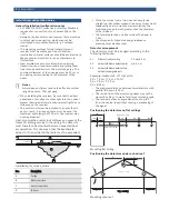
Heat accumulation under roof surfaces can prevent the
travel of climbing smoke to the ceiling. The detector
must therefore be mounted below an expected heat
accumulation. This can mean that the benchmark
values for D
L
specified in the table must be exceeded.
30-60 cm
C
B
A
D
installation_for_smoke_plume
Pos.
Description
A
Ceiling
B
Mushroom cloud
C
Heat accumulation
D
IR beam
• Since the smoke from a fire does not simply rise
straight up, but rather spreads like a mushroom cloud
(depending on air current and accumulation), the
monitoring range is much greater than the diameter
of the IR beam.
• The lateral detection on either side of the beam is
7.5 m.
• Country-specific Standards and guidelines on
planning must be observed.
Detector arrangement
The detectors must be arranged according to the
following distances:
X1
Distance from the ceiling
0.3 m to 0.6 m
X2
Horizontal distance detector/wall
min. 0.5 m
X3
Horizontal distance between two
detectors under gable roofs
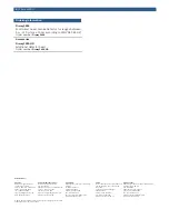
Example: Gable roof, 10° roof pitch
X3 = 7.5 m + (7.5 m x 10%)
X3 = 7.5 m + 0.75 m
X3 = 8.25 m
• The maximum distance between two detectors with
parallel IR beams is 15 m.
• The centre line of the monitoring beam may not be
closer than 0.5 m to walls, furniture or stored goods.
• The receivers allow an angle deviation of up to 5°
from the centre line without causing a weakening of
the signal.
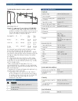
Positioning the detectors on flat ceilings
15m
7.5m
7.5m
0.3m < X1 < 0.6m
X1
X2
0.5m < X2 < 7.5m
15m
15m
Mounting flat ceiling
Positioning the detectors under a shed roof
X1
X2
10°
0.3 m < X1 < 0.6 m
X3
X3
0.5 m < X2 < 7.5 m
X2
Mounting shed roof
2 | Fireray3000


