


13
Model RT Energy Recovery Unit
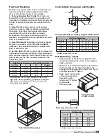
Curb Outside Dimensions and Weights
Roof Curb Mounting
Rooftop units require curbs to be mounted first. The
duct connections must be located so they will be
clear of structural members of the building.
1 Factory Supplied Roof Curbs:
Roof curbs are
Model GKD, which are shipped in a knockdown kit
(includes duct adapter) and require field assembly (by
others). Assembly instructions are included with the
curb.
2 Install Curb:
Locate curb over roof opening
and fasten in place. (Refer to Recommended Roof
Openings). Check that the diagonal dimensions
are within ±1/8 inch of each other and adjust
as necessary. For proper coil drainage and unit
operation, it is important that the installation be level.
Shim as required to level.
3 Install Ductwork:
Installation of all ducts should
be done in accordance with SMACNA and AMCA
guidelines. Duct adapter provided to support ducts
prior to setting the unit.
4 Set the Unit:
Lift unit to a point directly above the
curb and duct openings. Guide unit while lowering to
align with duct openings. Roof curbs fit inside the unit
base. Make sure the unit is properly seated on the
curb and is level.
Curb Outside Dimensions
Curb Cap Dimensions
Unit Size
A
B
C
D
E
RT-20
2.00
2.00
1.00
0.88
0.75
RT-45
2.00
4.25
2.00
1.31
0.50
RT-55
2.00
4.25
2.00
1.31
0.50
RT-90
2.00
4.25
2.00
1.31
0.50
All dimensions are in inches.
Rail Mounting
Unit Size
A
B
RT-20
5.0
41.0
RT-45
7.0
41.9
RT-55
5.5
53.0
RT-90
6.0
59.0
All dimensions are in inches.
Curb Outside Dimensions and Curb Weights (lbs)
Unit Size
L
W
Weight
RT-20
104.88
51.00
310
RT-45
115.75
60.63
400
RT-55
129.88
71.50
510
RT-90
148.13
90.75
720
All dimensions are in inches. Weights are for 12 inch
high curbs. Roof curb details, including duct locations
dimensions are available on RT roof curb assembly
instructions, part #468280
ROOF CURB
SIDE OF UNIT
BASE
1 INCH INSULATION
E
D
C
A
B
Curb Cap Details for Factory Supplied Roof Curbs
Rail Mounting / Layout
• Rails designed to handle the weight of the RT
should be positioned as shown on the diagram
(rails by others).
• Make sure that rail positioning does not interfere
with the supply air discharge opening or the
exhaust air intake opening on the RT unit. Avoid
area dimensioned “B” below.
• Rails should run the width
of the unit and extend
beyond the unit a
minimum of 12 inches
on each side.
• Set unit on rails.
B
A
Supply/Exhaust
Outdoor Air Intake Hood
Opening
Isometric view
of unit on rails
B
A
Supply/Exhaust
Outdoor Air Intake Hood
Opening
Side view of unit on rails