


18
en | Accessories
Conventional Automatic Detectors
F.01U.002.707 | 8.0 | 2011.10
Operation Guide
Bosch Sicherheitssysteme GmbH
5.7.1
Remote Indicator FAA-420-RI
Installation Notes
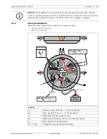
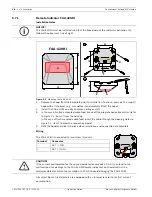
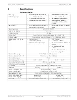
Figure 5.1
Mounting the FAA-420-RI
1.
Remove the hood from the baseplate prior to installation. To do so, press on the snap-fit
hook with a flat object (e. g. screwdriver) and carefully lift off the hood.
2.
Install the FAA-420-RI on a dry and even ceiling or wall.
3.
In the case of surface mounted cable feed, break off the pre-punched cable entries (refer
to
Figure 5.1
, item Z) from the housing.
In the case of flush mounted cable feed, insert the cable through the opening (refer to
Figure 5.1
, item Y) below the connection board.
4.
Refit the hood and click into place when installation and connection are complete.
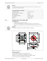
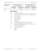
Wiring
The FAA-420-RI is connected to two screw terminals.
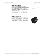
All current Bosch fire detectors are equipped with an internal resistor to restrict current
consumption.
NOTICE!
The FAA-420-RI must be installed such that the broad side of the red alarm indication (A)
follows the observer’s line of sight.
Terminal
Connector
-
GLT - / LSN -
+
GLT + / LSN +
1.
+
57
51
_
Y
A
X
31
Z
79
79
2.
FAA-420-RI
A
+
_
CAUTION!
If the current consumption for the connected detector exceeds 20 mA, it can lead to the
malfunction of or damage to the FAA-420-RI Remote Indicator.You should restrict the
maximum detector current consumption to 20 mA to avoid damaging the FAA-420-RI.
Summary of Contents for FCH?320
Page 1: ...Conventional Automatic Detectors FCP 320 FCH 320 en Operation Guide ...
Page 2: ......
Page 32: ......
Page 33: ......